Cirkit Designer Logo
Cirkit Designer
Your all-in-one circuit design IDE
Home / 
Component Documentation

How to Use TTL TO RS485 AUTO: Examples, Pinouts, and Specs

Image of TTL TO RS485 AUTO
Cirkit Designer LogoDesign with TTL TO RS485 AUTO in Cirkit Designer

Introduction

The TTL TO RS485 AUTO is a compact and efficient converter designed to automatically translate TTL (Transistor-Transistor Logic) signals to RS-485 signal levels. RS-485 is a widely used standard for serial communication, particularly in industrial and long-distance applications. This converter enables seamless communication between devices operating at different voltage levels, such as microcontrollers, sensors, and industrial equipment.

Explore Projects Built with TTL TO RS485 AUTO

Use Cirkit Designer to design, explore, and prototype these projects online. Some projects support real-time simulation. Click "Open Project" to start designing instantly!
Arduino UNO and Relay-Controlled RS485 Communication System
Image of Diagrama: A project utilizing TTL TO RS485 AUTO in a practical application
This circuit features an Arduino UNO microcontroller interfaced with a 4-channel relay module and a UART TTL to RS485 converter. The Arduino controls the relays via digital pins and communicates with the RS485 converter for serial communication, enabling control of external devices and communication over long distances.
Cirkit Designer LogoOpen Project in Cirkit Designer
STM32 and Arduino UNO Based Dual RS485 Communication Interface
Image of STM to Arduino RS485: A project utilizing TTL TO RS485 AUTO in a practical application
This circuit consists of two microcontrollers, an STM32F103C8T6 and an Arduino UNO, each interfaced with separate RS485 transceiver modules for serial communication. The STM32F103C8T6 controls the RE (Receiver Enable) and DE (Driver Enable) pins of one RS485 module to manage its operation, and communicates via the A9 and A10 pins for DI (Data Input) and RO (Receiver Output), respectively. The Arduino UNO is similarly connected to another RS485 module, with digital pins D2 and D3 interfacing with DI and RO, and D8 controlling both RE and DE. The RS485 modules are connected to each other through their A and B differential communication lines, enabling serial data exchange between the two microcontrollers over a robust and long-distance capable RS485 network.
Cirkit Designer LogoOpen Project in Cirkit Designer
Arduino UNO Based RS-485 Communication System with Pushbutton Activation and LED Indicator
Image of tp: A project utilizing TTL TO RS485 AUTO in a practical application
This circuit consists of two Arduino UNO microcontrollers interfaced with RS-485 modules to enable serial communication over a differential bus, allowing for robust long-distance data transmission. One Arduino is configured as a master, sending a message when a pushbutton is pressed, while the other Arduino is set up as a slave, responding by lighting up an LED when the correct message is received. The system is powered by two separate 9V batteries, and a resistor is used to limit the current through the LED.
Cirkit Designer LogoOpen Project in Cirkit Designer
RS485-Enabled NPK Soil Sensor Interface
Image of NPK: A project utilizing TTL TO RS485 AUTO in a practical application
This circuit connects an NPK Soil Sensor to an RS485 transceiver module. The sensor's VCC and GND pins are connected to the corresponding VCC and GND pins on the RS485 module to provide power. The sensor's analog output (A) and digital output (B) are interfaced with the RS485 module's DI (Data Input) and DE (Driver Enable) pins, respectively, allowing the sensor's signals to be transmitted over an RS485 communication bus.
Cirkit Designer LogoOpen Project in Cirkit Designer

Explore Projects Built with TTL TO RS485 AUTO

Use Cirkit Designer to design, explore, and prototype these projects online. Some projects support real-time simulation. Click "Open Project" to start designing instantly!
Image of Diagrama: A project utilizing TTL TO RS485 AUTO in a practical application
Arduino UNO and Relay-Controlled RS485 Communication System
This circuit features an Arduino UNO microcontroller interfaced with a 4-channel relay module and a UART TTL to RS485 converter. The Arduino controls the relays via digital pins and communicates with the RS485 converter for serial communication, enabling control of external devices and communication over long distances.
Cirkit Designer LogoOpen Project in Cirkit Designer
Image of STM to Arduino RS485: A project utilizing TTL TO RS485 AUTO in a practical application
STM32 and Arduino UNO Based Dual RS485 Communication Interface
This circuit consists of two microcontrollers, an STM32F103C8T6 and an Arduino UNO, each interfaced with separate RS485 transceiver modules for serial communication. The STM32F103C8T6 controls the RE (Receiver Enable) and DE (Driver Enable) pins of one RS485 module to manage its operation, and communicates via the A9 and A10 pins for DI (Data Input) and RO (Receiver Output), respectively. The Arduino UNO is similarly connected to another RS485 module, with digital pins D2 and D3 interfacing with DI and RO, and D8 controlling both RE and DE. The RS485 modules are connected to each other through their A and B differential communication lines, enabling serial data exchange between the two microcontrollers over a robust and long-distance capable RS485 network.
Cirkit Designer LogoOpen Project in Cirkit Designer
Image of tp: A project utilizing TTL TO RS485 AUTO in a practical application
Arduino UNO Based RS-485 Communication System with Pushbutton Activation and LED Indicator
This circuit consists of two Arduino UNO microcontrollers interfaced with RS-485 modules to enable serial communication over a differential bus, allowing for robust long-distance data transmission. One Arduino is configured as a master, sending a message when a pushbutton is pressed, while the other Arduino is set up as a slave, responding by lighting up an LED when the correct message is received. The system is powered by two separate 9V batteries, and a resistor is used to limit the current through the LED.
Cirkit Designer LogoOpen Project in Cirkit Designer
Image of NPK: A project utilizing TTL TO RS485 AUTO in a practical application
RS485-Enabled NPK Soil Sensor Interface
This circuit connects an NPK Soil Sensor to an RS485 transceiver module. The sensor's VCC and GND pins are connected to the corresponding VCC and GND pins on the RS485 module to provide power. The sensor's analog output (A) and digital output (B) are interfaced with the RS485 module's DI (Data Input) and DE (Driver Enable) pins, respectively, allowing the sensor's signals to be transmitted over an RS485 communication bus.
Cirkit Designer LogoOpen Project in Cirkit Designer

Common Applications and Use Cases

  • Connecting microcontrollers (e.g., Arduino, Raspberry Pi) to RS-485 networks
  • Industrial automation and control systems
  • Long-distance serial communication (up to 1200 meters)
  • Interfacing with RS-485-based devices like motor controllers, sensors, and PLCs
  • Multi-device communication in a half-duplex RS-485 network

Technical Specifications

Key Technical Details

  • Input Signal: TTL (3.3V or 5V logic levels)
  • Output Signal: RS-485 differential signal
  • Communication Mode: Half-duplex (automatic direction control)
  • Baud Rate: Up to 115200 bps
  • Operating Voltage: 3.3V or 5V DC
  • Power Consumption: Low power consumption (< 20mA typical)
  • Communication Distance: Up to 1200 meters (depending on cable quality and baud rate)
  • Operating Temperature: -40°C to 85°C
  • Dimensions: Compact PCB module, typically 25mm x 15mm

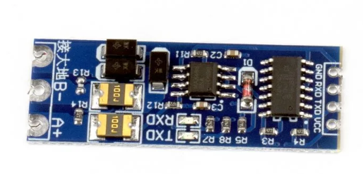
Pin Configuration and Descriptions

The TTL TO RS485 AUTO module typically has the following pin layout:

Pin Name Type Description
VCC Power Input Connect to 3.3V or 5V DC power supply.
GND Ground Connect to the ground of the power supply and circuit.
TXD TTL Input Transmit data from the microcontroller or TTL device.
RXD TTL Output Receive data to the microcontroller or TTL device.
A (D+) RS-485 Output Non-inverting RS-485 signal line (connect to RS-485 device or network).
B (D-) RS-485 Output Inverting RS-485 signal line (connect to RS-485 device or network).

Usage Instructions

How to Use the Component in a Circuit

  1. Power the Module: Connect the VCC pin to a 3.3V or 5V DC power source and the GND pin to the ground.
  2. Connect TTL Signals:
    • Connect the TXD pin to the transmit pin (e.g., TX) of your microcontroller.
    • Connect the RXD pin to the receive pin (e.g., RX) of your microcontroller.
  3. Connect RS-485 Signals:
    • Connect the A (D+) pin to the non-inverting line of the RS-485 device or network.
    • Connect the B (D-) pin to the inverting line of the RS-485 device or network.
  4. Automatic Direction Control: The module automatically manages the direction of data flow, so no additional control pins are required.
  5. Termination Resistor (Optional): For long-distance communication, you may need to add a 120-ohm termination resistor between the A and B lines at both ends of the RS-485 network.

Important Considerations and Best Practices

  • Ensure that the power supply voltage matches the module's operating voltage (3.3V or 5V).
  • Use twisted-pair cables for RS-485 connections to minimize noise and signal degradation.
  • Avoid exceeding the maximum communication distance and baud rate for reliable operation.
  • If multiple devices are connected to the RS-485 network, ensure proper termination and biasing resistors are used.
  • Always connect the ground of the TTL device and the RS-485 network to ensure a common reference.

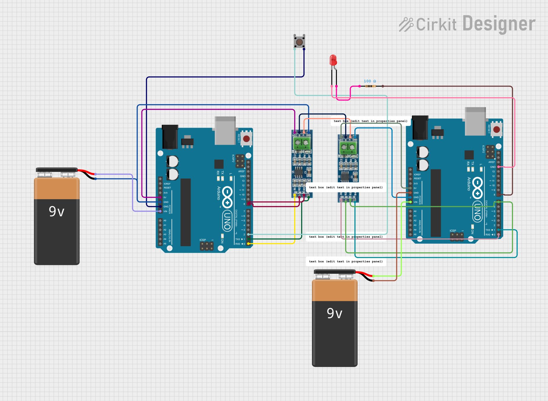
Example: Connecting to an Arduino UNO

Below is an example of how to use the TTL TO RS485 AUTO module with an Arduino UNO to send and receive data over an RS-485 network.

Circuit Diagram

  • Connect VCC to the Arduino's 5V pin.
  • Connect GND to the Arduino's GND pin.
  • Connect TXD to the Arduino's TX (pin 1).
  • Connect RXD to the Arduino's RX (pin 0).
  • Connect A (D+) and B (D-) to the RS-485 network.

Arduino Code Example

// Example code for using TTL TO RS485 AUTO with Arduino UNO
// This code sends and receives data over RS-485

void setup() {
  Serial.begin(9600); // Initialize serial communication at 9600 baud
  delay(1000);        // Wait for the module to initialize
  Serial.println("RS-485 Communication Started");
}

void loop() {
  // Send data over RS-485
  Serial.println("Hello RS-485");
  delay(1000); // Wait for 1 second

  // Check if data is available to read
  if (Serial.available() > 0) {
    String receivedData = Serial.readString(); // Read incoming data
    Serial.print("Received: ");
    Serial.println(receivedData); // Print received data
  }
}

Troubleshooting and FAQs

Common Issues and Solutions

  1. No Communication or Data Loss:

    • Ensure the A (D+) and B (D-) lines are correctly connected to the RS-485 network.
    • Verify that the baud rate of all devices on the RS-485 network matches.
    • Check for proper termination resistors at both ends of the RS-485 network.
  2. Module Overheating:

    • Ensure the power supply voltage does not exceed the module's operating range.
    • Check for short circuits or incorrect wiring.
  3. Noise or Signal Interference:

    • Use shielded or twisted-pair cables for RS-485 connections.
    • Ensure the ground of all devices in the network is properly connected.
  4. Automatic Direction Control Not Working:

    • Verify that the module is receiving sufficient power.
    • Ensure the TTL signals are within the acceptable voltage range (3.3V or 5V).

FAQs

Q: Can this module be used for full-duplex communication?
A: No, the TTL TO RS485 AUTO module supports only half-duplex communication, meaning data transmission and reception occur on the same pair of wires but not simultaneously.

Q: What is the maximum number of devices that can be connected to an RS-485 network?
A: RS-485 supports up to 32 devices on a single network without additional repeaters.

Q: Can I use this module with a 3.3V microcontroller?
A: Yes, the module is compatible with both 3.3V and 5V logic levels. Ensure the VCC pin is connected to the appropriate voltage.

Q: Do I need to manually control the data direction?
A: No, the module features automatic direction control, so no additional control pins are required.