Cirkit Designer Logo
Cirkit Designer
Your all-in-one circuit design IDE
Home / 
Component Documentation

How to Use TXS0108E High Speed Full Duplex Shifter 8 Way 8 Channel Logic Level Conversion Module 8-Bit 8 CH: Examples, Pinouts, and Specs

Image of TXS0108E High Speed Full Duplex Shifter 8 Way 8 Channel Logic Level Conversion Module 8-Bit 8 CH
Cirkit Designer LogoDesign with TXS0108E High Speed Full Duplex Shifter 8 Way 8 Channel Logic Level Conversion Module 8-Bit 8 CH in Cirkit Designer

Introduction

The TXS0108E by DEVMO is an 8-channel bidirectional logic level converter designed to facilitate communication between devices operating at different voltage levels. It supports high-speed, full-duplex voltage translation, making it ideal for modern digital systems where multiple voltage domains coexist. This module is particularly useful for interfacing microcontrollers, sensors, and other peripherals that operate at different logic levels, such as 1.8V, 3.3V, and 5V.

Explore Projects Built with TXS0108E High Speed Full Duplex Shifter 8 Way 8 Channel Logic Level Conversion Module 8-Bit 8 CH

Use Cirkit Designer to design, explore, and prototype these projects online. Some projects support real-time simulation. Click "Open Project" to start designing instantly!
Wi-Fi Controlled Device Interface with Wemos D1 Mini and Logic Level Converter
Image of Toshiba AC D1 mini: A project utilizing TXS0108E High Speed Full Duplex Shifter 8 Way 8 Channel Logic Level Conversion Module 8-Bit 8 CH in a practical application
This circuit features a Wemos D1 Mini microcontroller interfaced with a Bi-Directional Logic Level Converter to facilitate communication with a 5V RX/TX module. The level converter ensures proper voltage translation between the 3.3V logic of the Wemos D1 Mini and the 5V logic of the RX/TX module.
Cirkit Designer LogoOpen Project in Cirkit Designer
Arduino Mega 2560 Controlled Motor System with I2C Communication and Hall Effect Sensing
Image of Uni1: A project utilizing TXS0108E High Speed Full Duplex Shifter 8 Way 8 Channel Logic Level Conversion Module 8-Bit 8 CH in a practical application
This is a motor control system with feedback and sensor integration. It uses an Arduino Mega 2560 to control MD03 motor drivers for DC motors, receives position and speed feedback from HEDS encoders and Hall sensors, and measures distance with SR02 ultrasonic sensors. Logic level converters ensure compatibility between different voltage levels of the components.
Cirkit Designer LogoOpen Project in Cirkit Designer
ESP32 and Logic Level Converter-Based Wi-Fi Controlled Interface
Image of Toshiba AC ESP32 devkit v1: A project utilizing TXS0108E High Speed Full Duplex Shifter 8 Way 8 Channel Logic Level Conversion Module 8-Bit 8 CH in a practical application
This circuit features an ESP32 Devkit V1 microcontroller connected to a Bi-Directional Logic Level Converter, which facilitates voltage level shifting between the ESP32 and external components. The ESP32 is powered through its VIN pin via an alligator clip cable, and the logic level converter is connected to various pins on the ESP32 to manage different voltage levels for communication.
Cirkit Designer LogoOpen Project in Cirkit Designer
Arduino Nano-Based Smart Relay Controller with RS485 Communication
Image of RELAY RS485: A project utilizing TXS0108E High Speed Full Duplex Shifter 8 Way 8 Channel Logic Level Conversion Module 8-Bit 8 CH in a practical application
This circuit features an Arduino Nano controlling an 8-channel relay module, with each relay channel connected to digital pins D2 through D9. Additionally, the Arduino interfaces with an RS485 module for serial communication, which is connected to an RS485 to USB converter. Power is supplied through an LM2596 step-down module.
Cirkit Designer LogoOpen Project in Cirkit Designer

Explore Projects Built with TXS0108E High Speed Full Duplex Shifter 8 Way 8 Channel Logic Level Conversion Module 8-Bit 8 CH

Use Cirkit Designer to design, explore, and prototype these projects online. Some projects support real-time simulation. Click "Open Project" to start designing instantly!
Image of Toshiba AC D1 mini: A project utilizing TXS0108E High Speed Full Duplex Shifter 8 Way 8 Channel Logic Level Conversion Module 8-Bit 8 CH in a practical application
Wi-Fi Controlled Device Interface with Wemos D1 Mini and Logic Level Converter
This circuit features a Wemos D1 Mini microcontroller interfaced with a Bi-Directional Logic Level Converter to facilitate communication with a 5V RX/TX module. The level converter ensures proper voltage translation between the 3.3V logic of the Wemos D1 Mini and the 5V logic of the RX/TX module.
Cirkit Designer LogoOpen Project in Cirkit Designer
Image of Uni1: A project utilizing TXS0108E High Speed Full Duplex Shifter 8 Way 8 Channel Logic Level Conversion Module 8-Bit 8 CH in a practical application
Arduino Mega 2560 Controlled Motor System with I2C Communication and Hall Effect Sensing
This is a motor control system with feedback and sensor integration. It uses an Arduino Mega 2560 to control MD03 motor drivers for DC motors, receives position and speed feedback from HEDS encoders and Hall sensors, and measures distance with SR02 ultrasonic sensors. Logic level converters ensure compatibility between different voltage levels of the components.
Cirkit Designer LogoOpen Project in Cirkit Designer
Image of Toshiba AC ESP32 devkit v1: A project utilizing TXS0108E High Speed Full Duplex Shifter 8 Way 8 Channel Logic Level Conversion Module 8-Bit 8 CH in a practical application
ESP32 and Logic Level Converter-Based Wi-Fi Controlled Interface
This circuit features an ESP32 Devkit V1 microcontroller connected to a Bi-Directional Logic Level Converter, which facilitates voltage level shifting between the ESP32 and external components. The ESP32 is powered through its VIN pin via an alligator clip cable, and the logic level converter is connected to various pins on the ESP32 to manage different voltage levels for communication.
Cirkit Designer LogoOpen Project in Cirkit Designer
Image of RELAY RS485: A project utilizing TXS0108E High Speed Full Duplex Shifter 8 Way 8 Channel Logic Level Conversion Module 8-Bit 8 CH in a practical application
Arduino Nano-Based Smart Relay Controller with RS485 Communication
This circuit features an Arduino Nano controlling an 8-channel relay module, with each relay channel connected to digital pins D2 through D9. Additionally, the Arduino interfaces with an RS485 module for serial communication, which is connected to an RS485 to USB converter. Power is supplied through an LM2596 step-down module.
Cirkit Designer LogoOpen Project in Cirkit Designer

Common Applications and Use Cases

  • Interfacing 3.3V microcontrollers (e.g., Arduino, ESP32) with 5V peripherals.
  • Communication between low-voltage sensors and high-voltage controllers.
  • Voltage level translation in I2C, SPI, UART, and GPIO applications.
  • Mixed-voltage digital systems in IoT, robotics, and embedded systems.

Technical Specifications

The following table outlines the key technical details of the TXS0108E module:

Parameter Value
Manufacturer DEVMO
Part Number TXS0108E
Voltage Range (VCCA) 1.2V to 3.6V
Voltage Range (VCCB) 1.65V to 5.5V
Maximum Data Rate 110 Mbps (push-pull) / 1.2 Mbps (open-drain)
Channels 8
Operating Temperature Range -40°C to +85°C
Package Type SOP-20 (module form factor)

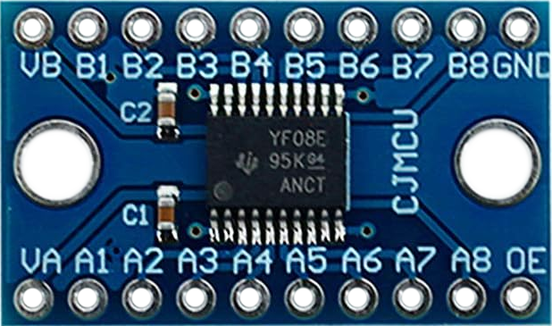
Pin Configuration and Descriptions

The TXS0108E module has 20 pins, with the following configuration:

Pin Name Description
1 VCCA Voltage supply for the low-voltage side (1.2V to 3.6V).
2-9 A1-A8 Low-voltage side I/O pins (correspond to B1-B8 for bidirectional translation).
10 GND Ground connection.
11-18 B1-B8 High-voltage side I/O pins (correspond to A1-A8 for bidirectional translation).
19 OE Output enable pin (active HIGH). Enables bidirectional translation.
20 VCCB Voltage supply for the high-voltage side (1.65V to 5.5V).

Usage Instructions

How to Use the TXS0108E in a Circuit

  1. Power Connections:

    • Connect the low-voltage supply (e.g., 3.3V) to the VCCA pin.
    • Connect the high-voltage supply (e.g., 5V) to the VCCB pin.
    • Ensure a common ground by connecting the GND pin to the ground of your circuit.
  2. I/O Connections:

    • Connect the low-voltage device's I/O pins to the A1-A8 pins.
    • Connect the high-voltage device's I/O pins to the corresponding B1-B8 pins.
  3. Enable Translation:

    • Set the OE pin HIGH to enable bidirectional voltage translation.
    • If the OE pin is LOW, all I/O pins are in a high-impedance state.
  4. Data Direction:

    • The TXS0108E automatically detects the direction of data flow, so no additional configuration is required.

Important Considerations and Best Practices

  • Ensure that VCCA is always less than or equal to VCCB.
  • Use decoupling capacitors (e.g., 0.1 µF) near the VCCA and VCCB pins to stabilize the power supply.
  • Avoid exceeding the maximum voltage ratings to prevent damage to the module.
  • For open-drain signals (e.g., I2C), use external pull-up resistors on both sides of the module.

Example: Connecting TXS0108E to an Arduino UNO

The following example demonstrates how to use the TXS0108E to interface a 3.3V sensor with a 5V Arduino UNO.

Circuit Diagram

  • VCCA: Connect to the 3.3V pin of the sensor.
  • VCCB: Connect to the 5V pin of the Arduino UNO.
  • GND: Connect to the common ground of the Arduino and sensor.
  • A1: Connect to the sensor's data pin.
  • B1: Connect to the Arduino's digital pin (e.g., D2).

Arduino Code Example

// Example: Reading data from a 3.3V sensor using TXS0108E and Arduino UNO

const int sensorPin = 2; // Arduino pin connected to TXS0108E B1
void setup() {
  pinMode(sensorPin, INPUT); // Set the pin as input
  Serial.begin(9600);        // Initialize serial communication
}

void loop() {
  int sensorValue = digitalRead(sensorPin); // Read sensor data
  Serial.println(sensorValue);              // Print the value to the Serial Monitor
  delay(500);                               // Wait for 500ms
}

Troubleshooting and FAQs

Common Issues and Solutions

  1. No Signal Translation:

    • Ensure the OE pin is set HIGH to enable the module.
    • Verify that VCCA and VCCB are within the specified voltage ranges.
  2. Unstable or Noisy Signals:

    • Add decoupling capacitors near the power supply pins.
    • Check for loose or poor connections in the circuit.
  3. Incorrect Voltage Levels:

    • Confirm that VCCA is less than or equal to VCCB.
    • Ensure the connected devices are operating within their respective voltage ranges.
  4. Module Overheating:

    • Check for short circuits or excessive current draw.
    • Verify that the module is not exposed to voltages beyond its maximum ratings.

FAQs

Q1: Can the TXS0108E be used for I2C communication?
Yes, the TXS0108E supports open-drain signals like I2C. However, you must use external pull-up resistors on both sides of the module.

Q2: What is the maximum data rate supported by the TXS0108E?
The module supports up to 110 Mbps for push-pull signals and 1.2 Mbps for open-drain signals.

Q3: Can I leave unused pins floating?
It is recommended to tie unused pins to ground or a known voltage level to avoid noise or interference.

Q4: Is the TXS0108E suitable for analog signals?
No, the TXS0108E is designed for digital signals only. For analog signals, use an appropriate level shifter or amplifier.