How to Use Servo (Wokwi Compatible): Examples, Pinouts, and Specs
Introduction
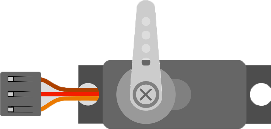
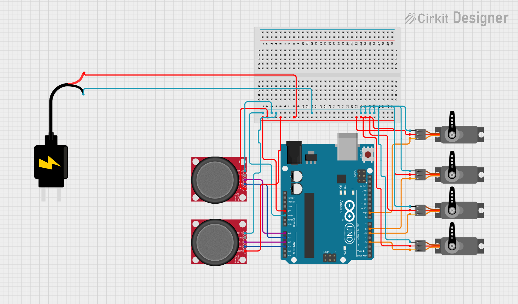
A Servo (Wokwi Compatible) is a type of rotary actuator that enables precise control over angular position. It integrates a motor with a position feedback sensor, typically through a gear system. This component is essential in various applications such as robotics, remote-controlled vehicles, and automated systems where precise movement and positioning are required.
Explore Projects Built with Servo (Wokwi Compatible)
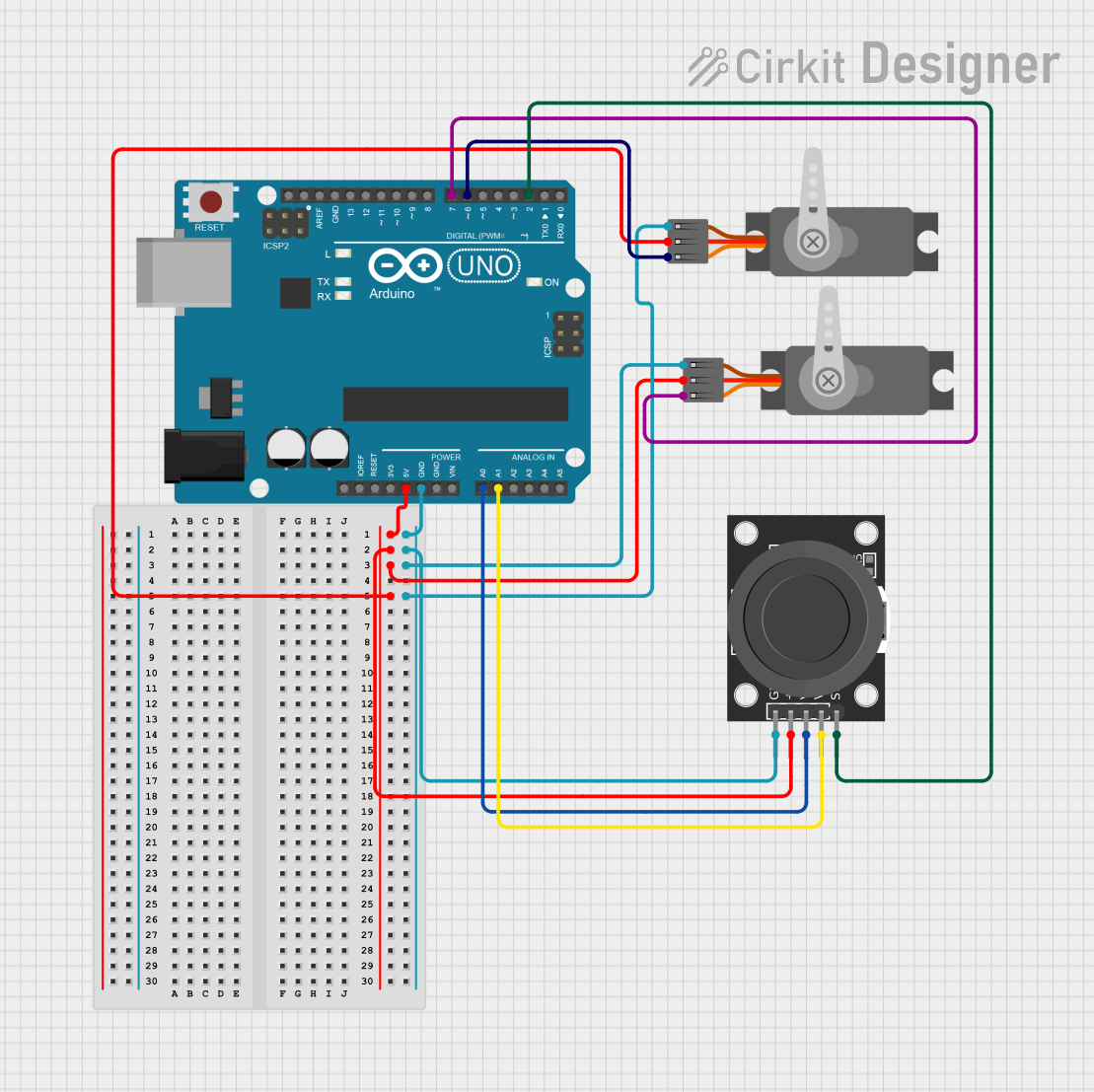
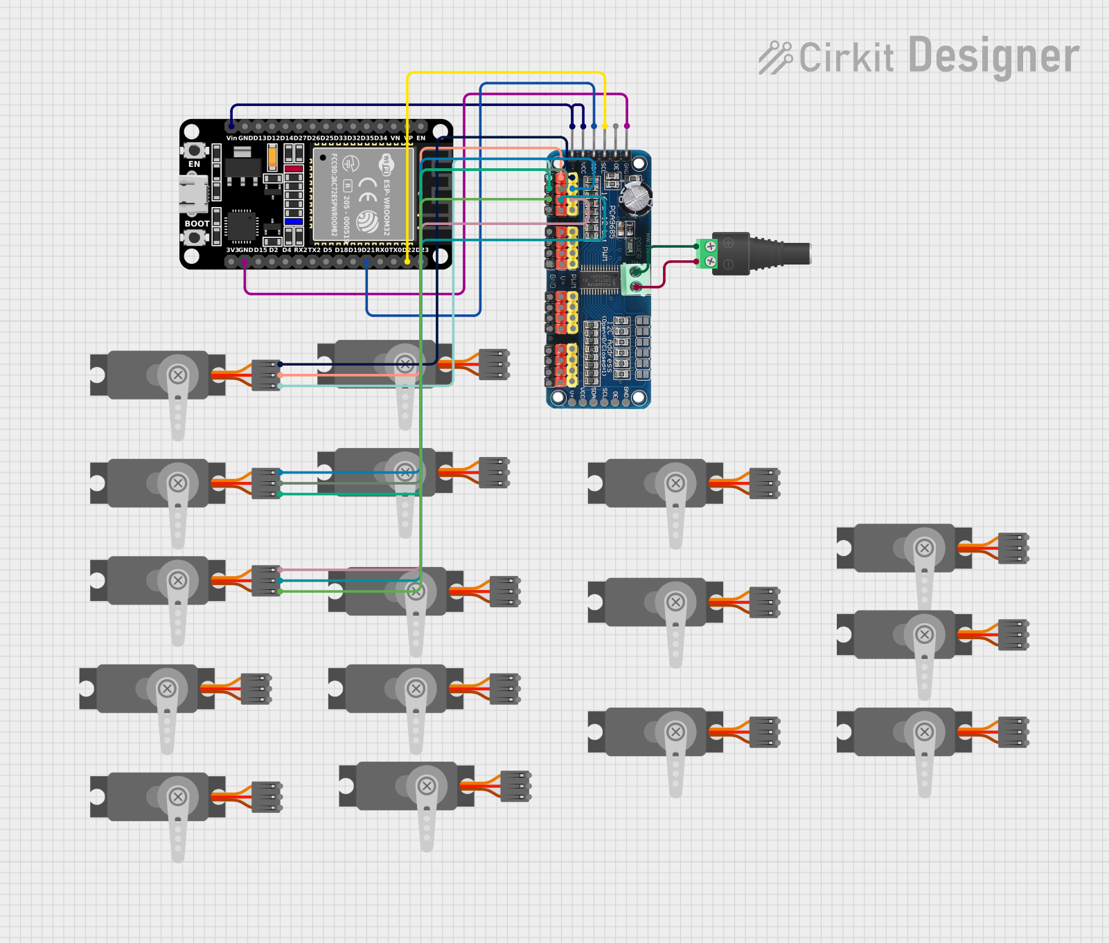
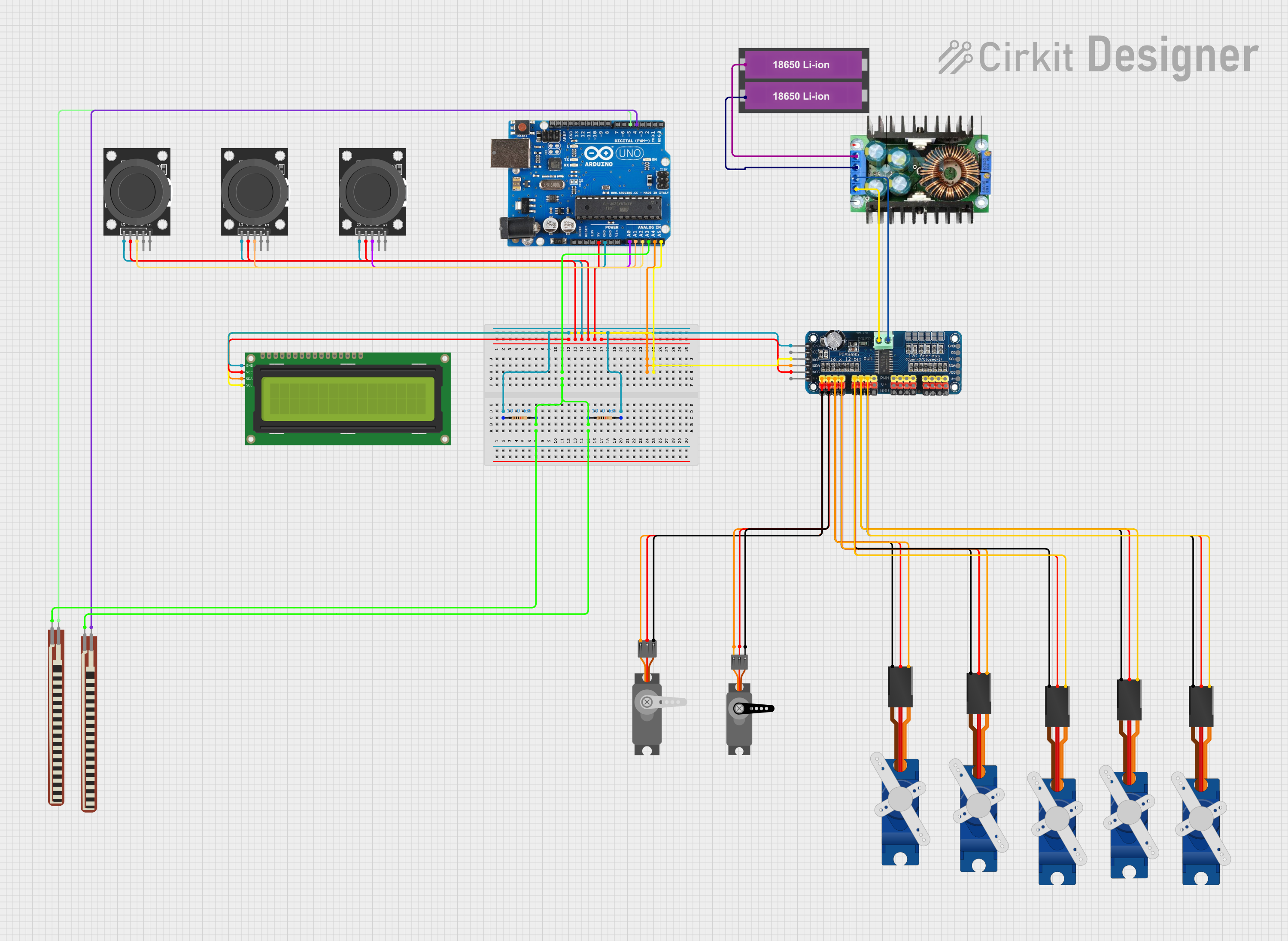
Explore Projects Built with Servo (Wokwi Compatible)
Common Applications and Use Cases
- Robotic arms and joints
- Steering mechanisms in RC vehicles
- Camera pan and tilt systems
- Automated doors and valves
- Animatronics
Technical Specifications
Key Technical Details
- Voltage: Typically 4.8V to 6V
- Current: Varies with load, typically around 100mA to 1A at stall
- Torque: Depends on model (e.g., 1.5 kg-cm to 20 kg-cm)
- Speed: Varies with model (e.g., 0.10 sec/60° to 0.24 sec/60°)
- Control Signal: PWM (Pulse Width Modulation), typically 1ms to 2ms pulse for 0° to 180°
Pin Configuration and Descriptions
| Pin Number | Name | Description |
|---|---|---|
| 1 | GND | Ground connection |
| 2 | VCC | Power supply (4.8V to 6V) |
| 3 | SIG | Control signal input (PWM) |
Usage Instructions
How to Use the Servo in a Circuit
- Power Supply: Connect the VCC pin to a suitable power supply (4.8V to 6V).
- Ground: Connect the GND pin to the ground of the power supply and the control board (e.g., Arduino UNO).
- Control Signal: Connect the SIG pin to a PWM-capable pin on the control board.
Important Considerations and Best Practices
- Ensure the power supply can handle the current requirements of the servo, especially under load.
- Avoid stalling the servo for extended periods as this can lead to overheating and damage.
- Use a separate power supply if the servo causes significant voltage drops that reset the control board.
- Keep the control signal within the specified pulse width range to prevent damage to the servo.
Example Code for Arduino UNO
#include <Servo.h>

Servo myservo;  // Create servo object to control a servo

void setup() {
  myservo.attach(9);  // Attaches the servo on pin 9 to the servo object
}

void loop() {
  myservo.write(90);  // Sets the servo position to 90°
  delay(1000);        // Wait for 1 second
  myservo.write(0);   // Sets the servo position to 0°
  delay(1000);        // Wait for 1 second
}
Troubleshooting and FAQs
Common Issues
- Servo not moving: Check connections, ensure the control signal is correct, and verify that the power supply is adequate.
- Erratic movement: This can be due to an insufficient power supply or noise in the control signal. Ensure a stable power source and signal.
- Overheating: If the servo is hot to the touch, it may be stalled or overloaded. Reduce the load or duty cycle.
Solutions and Tips for Troubleshooting
- Power Issues: Use a multimeter to check the voltage at the servo's power pins.
- Signal Issues: Use an oscilloscope to verify the PWM signal's pulse width.
- Mechanical Load: Ensure the servo is not trying to move beyond its physical limits or handle too much weight.
FAQs
Q: Can I control the servo with a constant voltage? A: No, servos require a PWM signal to set the position.
Q: What is the maximum angle my servo can rotate? A: Most servos have a range of 180 degrees, but it can vary by model. Check the datasheet for your specific servo.
Q: How can I reverse the direction of the servo? A: You can reverse the direction by swapping the pulse width values for the desired positions in your code.
Remember to always refer to the specific datasheet of the servo model you are using for the most accurate and detailed information.