Cirkit Designer Logo
Cirkit Designer
Your all-in-one circuit design IDE
Home / 
Component Documentation

How to Use Adafruit 2.0 inch 240x320 IPS TFT: Examples, Pinouts, and Specs

Image of Adafruit 2.0 inch 240x320 IPS TFT
Cirkit Designer LogoDesign with Adafruit 2.0 inch 240x320 IPS TFT in Cirkit Designer

Introduction

The Adafruit 2.0 inch 240x320 IPS TFT is a vibrant, high-resolution display module that is perfect for adding a small but high-quality screen to your electronics projects. With its In-Plane Switching (IPS) technology, it offers a wide viewing angle and accurate color reproduction, which makes it ideal for handheld devices, user interfaces, or any application where visual quality is paramount. This display is commonly used with microcontrollers like the Arduino UNO and single-board computers such as the Raspberry Pi.

Explore Projects Built with Adafruit 2.0 inch 240x320 IPS TFT

Use Cirkit Designer to design, explore, and prototype these projects online. Some projects support real-time simulation. Click "Open Project" to start designing instantly!
Arduino Mega 2560 Controlled TFT Touchscreen Interface
Image of Tablero Moto: A project utilizing Adafruit 2.0 inch 240x320 IPS TFT in a practical application
This circuit connects an Arduino Mega 2560 microcontroller to a 3.5-inch 480x320 TFT LCD display. The Arduino provides power, ground, and digital signals to control the display, including data lines for pixel information and control lines for reset, write, and command/data selection. The embedded code initializes the display and configures the Arduino's pins for communication, likely to create a user interface or visual output for a project.
Cirkit Designer LogoOpen Project in Cirkit Designer
Arduino UNO and ILI9341 TFT Display Interactive Graphics Demo
Image of CE Test ili9341: A project utilizing Adafruit 2.0 inch 240x320 IPS TFT in a practical application
This circuit interfaces an Arduino UNO with an ILI9341 TFT display using two bi-directional logic level converters to manage voltage differences. The Arduino runs a program to test various graphical functions on the TFT display, demonstrating its capabilities through a series of visual benchmarks.
Cirkit Designer LogoOpen Project in Cirkit Designer
Arduino Nano Controlled TFT Display with Multiple Pushbuttons
Image of rey: A project utilizing Adafruit 2.0 inch 240x320 IPS TFT in a practical application
This circuit features an Arduino Nano microcontroller connected to a ST7735 128x128 1.44 TFT I2C Color display and multiple pushbuttons. The display is interfaced with the Arduino via digital pins for control signals and SPI pins for data transfer. The pushbuttons are connected to various digital and analog input pins on the Arduino, likely intended for user input to control the display or other functions within the code.
Cirkit Designer LogoOpen Project in Cirkit Designer
ESP32-Based Health Monitoring System with TFT Display and RTC
Image of RemindeRx Circuit Design: A project utilizing Adafruit 2.0 inch 240x320 IPS TFT in a practical application
This circuit features an ESP32 microcontroller interfaced with an ILI9341 TFT display, a DS3231 RTC module, and a MAX30102 sensor for health monitoring. The ESP32 handles display updates and sensor data acquisition, while the ULN2003 driver controls a 28BYJ-48 stepper motor. The setup is designed for a health monitoring system with a graphical user interface.
Cirkit Designer LogoOpen Project in Cirkit Designer

Explore Projects Built with Adafruit 2.0 inch 240x320 IPS TFT

Use Cirkit Designer to design, explore, and prototype these projects online. Some projects support real-time simulation. Click "Open Project" to start designing instantly!
Image of Tablero Moto: A project utilizing Adafruit 2.0 inch 240x320 IPS TFT in a practical application
Arduino Mega 2560 Controlled TFT Touchscreen Interface
This circuit connects an Arduino Mega 2560 microcontroller to a 3.5-inch 480x320 TFT LCD display. The Arduino provides power, ground, and digital signals to control the display, including data lines for pixel information and control lines for reset, write, and command/data selection. The embedded code initializes the display and configures the Arduino's pins for communication, likely to create a user interface or visual output for a project.
Cirkit Designer LogoOpen Project in Cirkit Designer
Image of CE Test ili9341: A project utilizing Adafruit 2.0 inch 240x320 IPS TFT in a practical application
Arduino UNO and ILI9341 TFT Display Interactive Graphics Demo
This circuit interfaces an Arduino UNO with an ILI9341 TFT display using two bi-directional logic level converters to manage voltage differences. The Arduino runs a program to test various graphical functions on the TFT display, demonstrating its capabilities through a series of visual benchmarks.
Cirkit Designer LogoOpen Project in Cirkit Designer
Image of rey: A project utilizing Adafruit 2.0 inch 240x320 IPS TFT in a practical application
Arduino Nano Controlled TFT Display with Multiple Pushbuttons
This circuit features an Arduino Nano microcontroller connected to a ST7735 128x128 1.44 TFT I2C Color display and multiple pushbuttons. The display is interfaced with the Arduino via digital pins for control signals and SPI pins for data transfer. The pushbuttons are connected to various digital and analog input pins on the Arduino, likely intended for user input to control the display or other functions within the code.
Cirkit Designer LogoOpen Project in Cirkit Designer
Image of RemindeRx Circuit Design: A project utilizing Adafruit 2.0 inch 240x320 IPS TFT in a practical application
ESP32-Based Health Monitoring System with TFT Display and RTC
This circuit features an ESP32 microcontroller interfaced with an ILI9341 TFT display, a DS3231 RTC module, and a MAX30102 sensor for health monitoring. The ESP32 handles display updates and sensor data acquisition, while the ULN2003 driver controls a 28BYJ-48 stepper motor. The setup is designed for a health monitoring system with a graphical user interface.
Cirkit Designer LogoOpen Project in Cirkit Designer

Technical Specifications

General Features

  • Display Size: 2.0 inches diagonal
  • Resolution: 240x320 pixels
  • Display Technology: IPS TFT
  • Interface: SPI (Serial Peripheral Interface)
  • Operating Voltage: 3.3V to 5V logic
  • Current Draw: Typically 20mA (depends on backlight brightness)
  • Operating Temperature: -20°C to 70°C
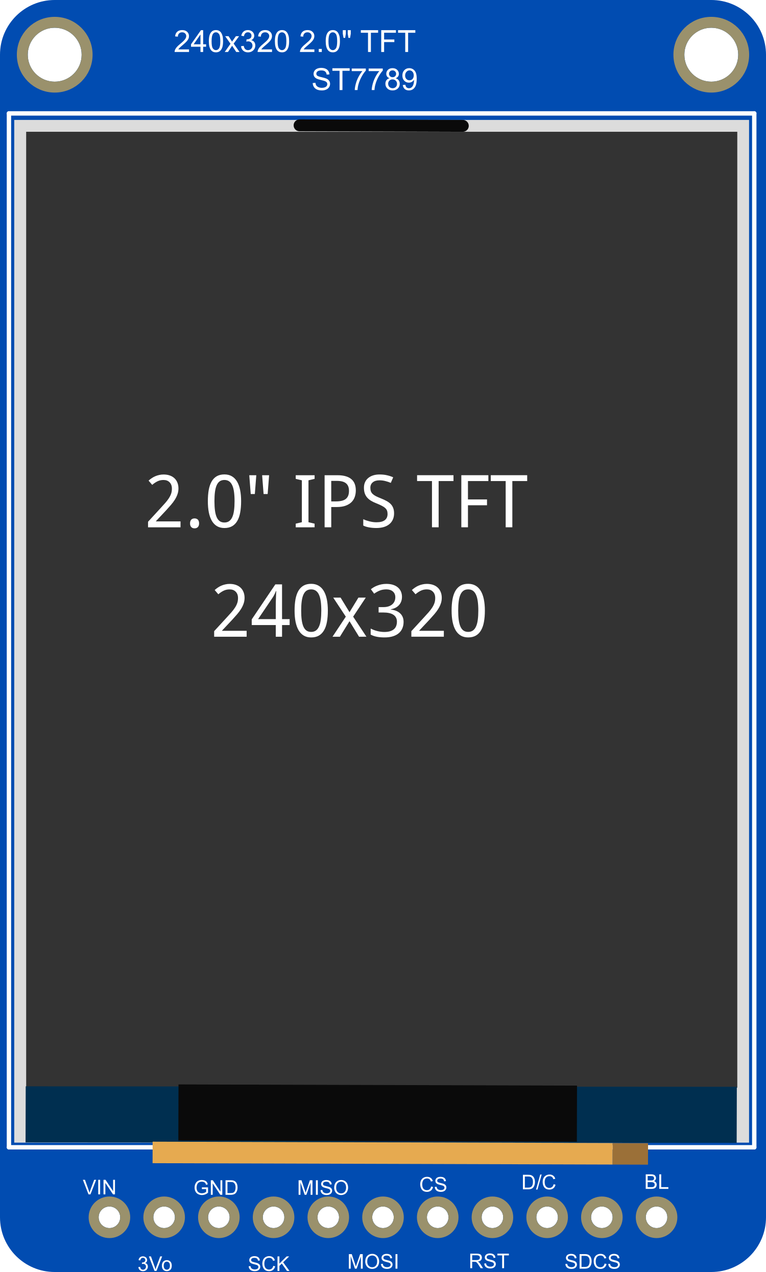
Pin Configuration

Pin Number Name Description
1 GND Ground connection
2 VCC Power supply (3.3V-5V)
3 SCK SPI clock
4 MOSI SPI Master Out Slave In
5 CS Chip Select for SPI
6 D/C Data/Command control pin
7 RST Reset pin
8 BL Backlight control (PWM capable)

Usage Instructions

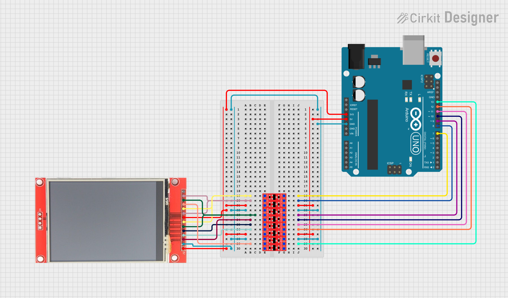
Wiring the Display to an Arduino UNO

  1. Connect GND to the ground pin on the Arduino.
  2. Connect VCC to the 5V out pin on the Arduino.
  3. Connect SCK to digital pin 13 (SCK) on the Arduino.
  4. Connect MOSI to digital pin 11 (MOSI) on the Arduino.
  5. Connect CS to a selectable digital pin, for example, digital pin 10.
  6. Connect D/C to another selectable digital pin, for example, digital pin 9.
  7. Connect RST to another selectable digital pin, for example, digital pin 8.
  8. Connect BL to a PWM-capable pin if you wish to control the backlight brightness, for example, digital pin 6.

Initializing the Display with Arduino

To use the display with an Arduino, you will need to install the Adafruit GFX library and the specific library for the display, which can be found in the Arduino Library Manager.

Here is a simple example code to initialize the display and show some basic graphics:

#include <Adafruit_GFX.h>    // Core graphics library
#include <Adafruit_TFTLCD.h> // Hardware-specific library

#define CS   10
#define DC   9
#define RST  8  // You can also connect this to the Arduino reset

Adafruit_TFTLCD tft(CS, DC, RST);

void setup() {
  tft.begin(); // Initialize the display
  tft.setRotation(1); // Set the rotation
  tft.fillScreen(BLACK); // Clear the screen to black
}

void loop() {
  // Your code to draw on the display goes here
}

Best Practices

  • Always ensure that the power supply voltage matches the requirements of the display.
  • Use a level shifter if you are interfacing with a 5V microcontroller.
  • Avoid exposing the display to direct sunlight for extended periods to prevent damage.
  • Handle the display with care to avoid pressure on the screen and connections.

Troubleshooting and FAQs

Common Issues

  • Display not powering on: Check the wiring, especially the power connections, and ensure that the correct voltage is supplied.
  • No image or incorrect colors: Verify that the SPI connections are correct and that the correct pins are used in your code.
  • Dim or flickering backlight: Ensure that the backlight pin (BL) is connected properly and that the PWM signal is stable if you are using PWM control.

FAQs

Q: Can I use this display with a 5V Arduino? A: Yes, but make sure to use a level shifter for the data lines to protect the display.

Q: How can I adjust the brightness of the backlight? A: You can connect the BL pin to a PWM-capable pin on your microcontroller and use analogWrite() to adjust the brightness.

Q: What library should I use for this display? A: The Adafruit GFX library along with the Adafruit TFTLCD library is recommended for this display.

For further assistance, consult the Adafruit forums or the community around the specific microcontroller you are using.