
How to Use DRV8833 Dual Motor Driver Carrier: Examples, Pinouts, and Specs
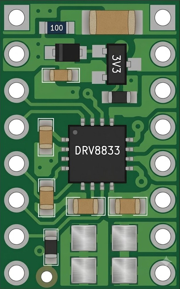
 Design with DRV8833 Dual Motor Driver Carrier in Cirkit Designer
Introduction
The DRV8833 Dual Motor Driver Carrier, manufactured by Pololu (Part ID: DRV8833), is a compact and efficient dual H-bridge motor driver. It is designed to control two DC motors or one bipolar stepper motor, making it ideal for robotics, automation, and other motor control applications. This module features built-in protection mechanisms, including overcurrent protection and thermal shutdown, ensuring reliable operation in demanding environments.
Explore Projects Built with DRV8833 Dual Motor Driver Carrier
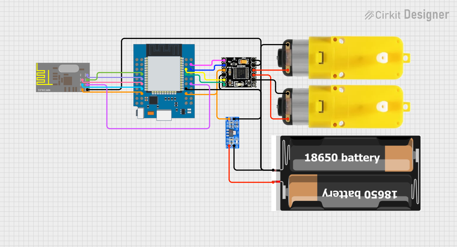 Open Project in Cirkit Designer
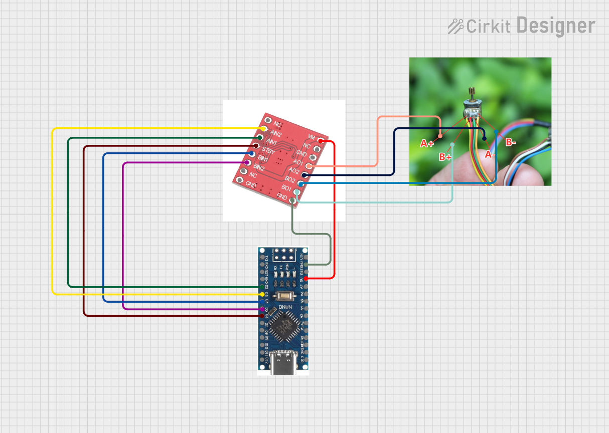 Open Project in Cirkit Designer
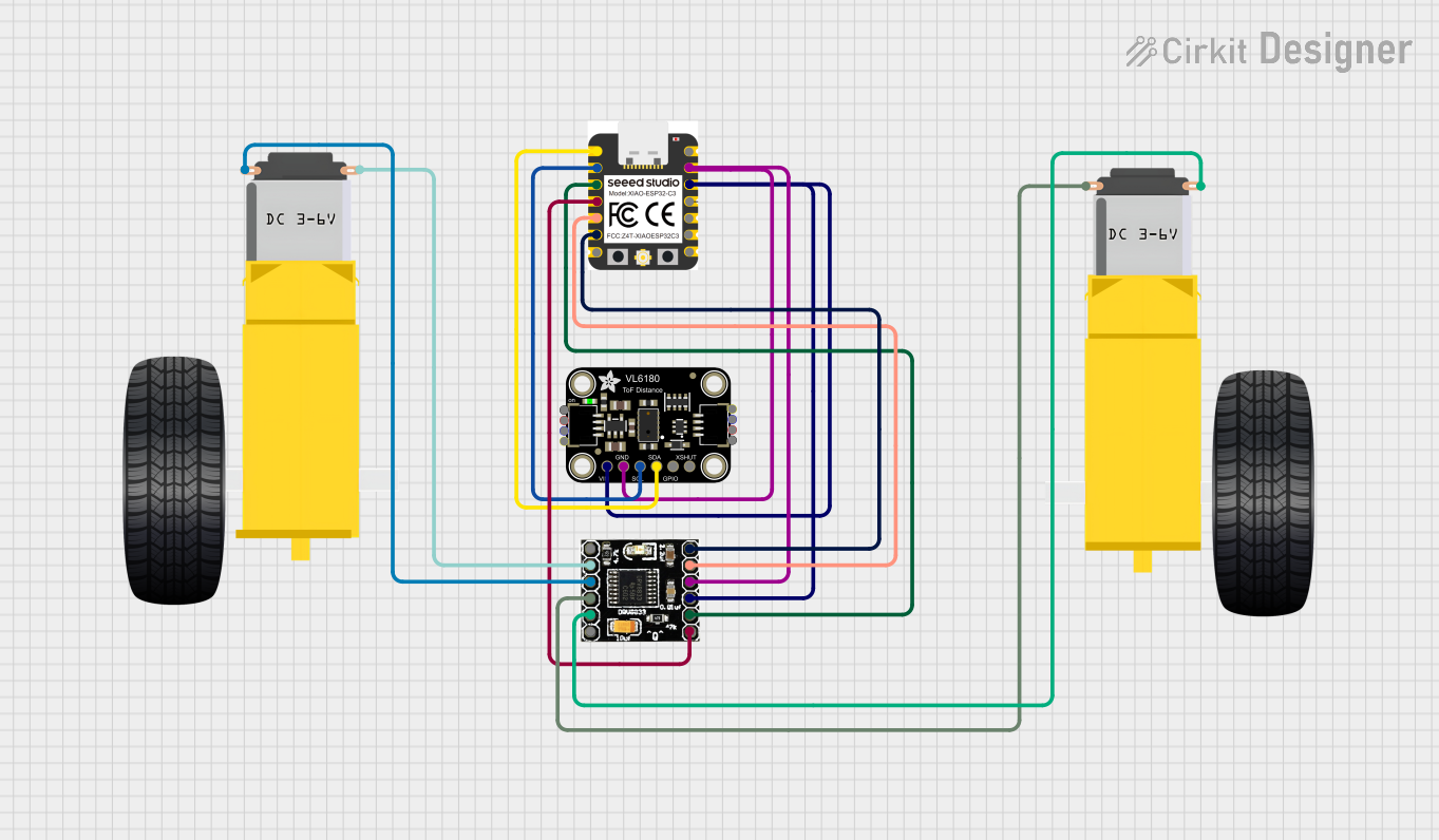 Open Project in Cirkit Designer
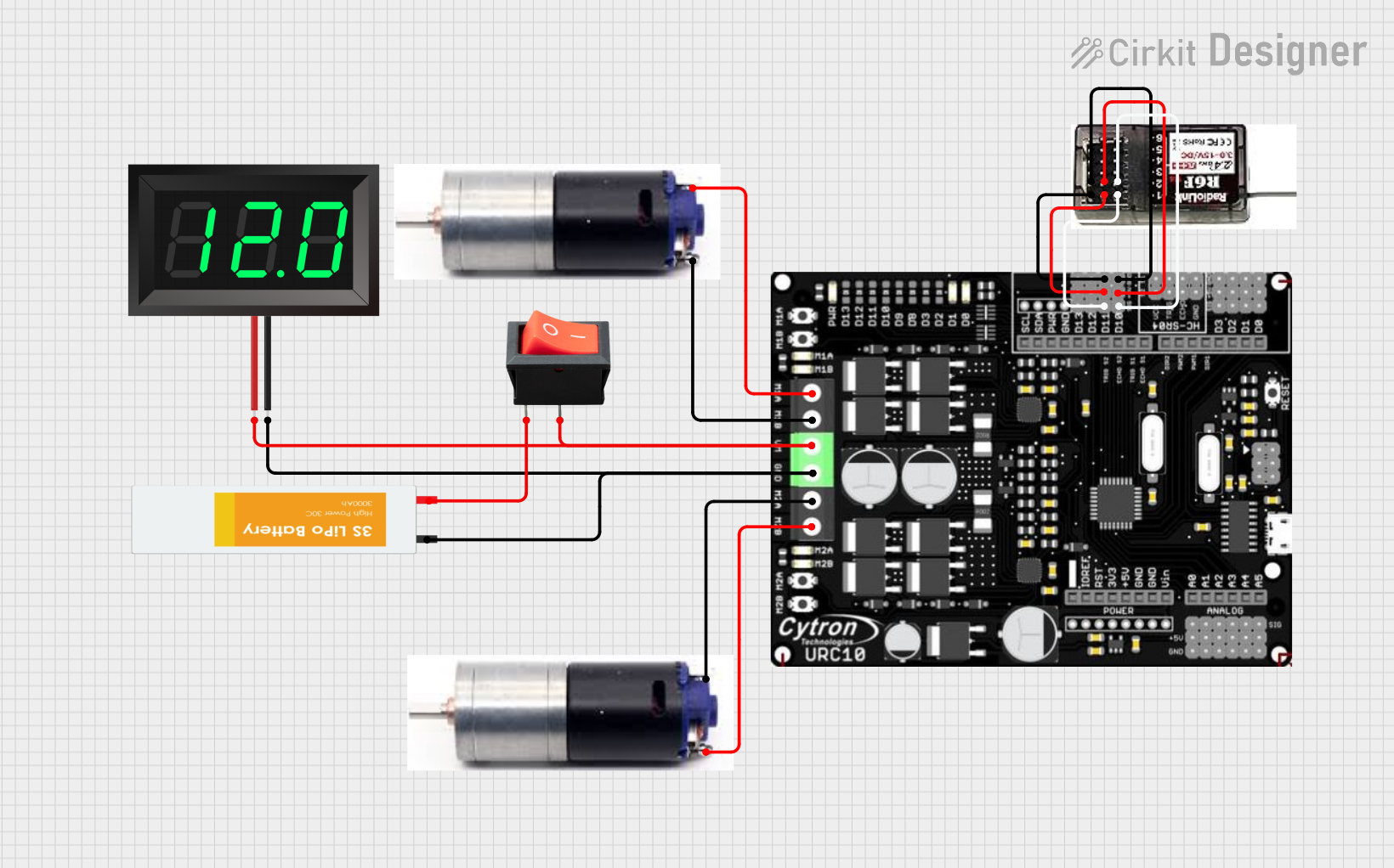 Open Project in Cirkit Designer
Explore Projects Built with DRV8833 Dual Motor Driver Carrier
Open Project in Cirkit DesignerOpen Project in Cirkit DesignerOpen Project in Cirkit DesignerOpen Project in Cirkit DesignerCommon Applications
- Robotics and automation systems
- Remote-controlled vehicles
- Conveyor belts and motorized platforms
- Stepper motor control for 3D printers and CNC machines
- Educational and hobbyist projects
Technical Specifications
The DRV8833 is a versatile motor driver with the following key specifications:
| Parameter | Value |
|---|---|
| Operating Voltage (VCC) | 2.7 V to 10.8 V |
| Motor Output Current (per channel) | 1.2 A continuous, 2 A peak |
| Logic Voltage (VIN) | 1.8 V to 7 V |
| PWM Frequency | Up to 250 kHz |
| Built-in Protections | Overcurrent, thermal shutdown, undervoltage |
| Dimensions | 0.6" × 0.8" × 0.1" (15 mm × 20 mm × 3 mm) |
| Weight | 0.5 g |
Pin Configuration and Descriptions
The DRV8833 module has 10 pins, as described in the table below:
| Pin | Name | Description |
|---|---|---|
| 1 | VM | Motor power supply (2.7 V to 10.8 V). Connect to the motor power source. |
| 2 | GND | Ground connection. Common ground for logic and motor power. |
| 3 | AIN1 | Input 1 for Motor A. Controls direction and speed with PWM. |
| 4 | AIN2 | Input 2 for Motor A. Controls direction and speed with PWM. |
| 5 | BIN1 | Input 1 for Motor B. Controls direction and speed with PWM. |
| 6 | BIN2 | Input 2 for Motor B. Controls direction and speed with PWM. |
| 7 | AO1 | Output 1 for Motor A. Connect to one terminal of Motor A. |
| 8 | AO2 | Output 2 for Motor A. Connect to the other terminal of Motor A. |
| 9 | BO1 | Output 1 for Motor B. Connect to one terminal of Motor B. |
| 10 | BO2 | Output 2 for Motor B. Connect to the other terminal of Motor B. |
Usage Instructions
Connecting the DRV8833 to a Circuit
- Power Supply: Connect the VM pin to a motor power supply (2.7 V to 10.8 V). Ensure the power supply can provide sufficient current for your motors.
- Logic Voltage: Connect the control pins (AIN1, AIN2, BIN1, BIN2) to a microcontroller or logic circuit. These pins accept voltages between 1.8 V and 7 V.
- Motor Connections: Connect the motor terminals to AO1/AO2 (Motor A) and BO1/BO2 (Motor B).
- Ground: Connect the GND pin to the ground of your power supply and microcontroller.
Controlling Motors with an Arduino UNO
Below is an example code snippet to control two DC motors using the DRV8833 and an Arduino UNO:
// Define motor control pins
const int AIN1 = 3; // Motor A input 1
const int AIN2 = 4; // Motor A input 2
const int BIN1 = 5; // Motor B input 1
const int BIN2 = 6; // Motor B input 2

void setup() {
  // Set motor control pins as outputs
  pinMode(AIN1, OUTPUT);
  pinMode(AIN2, OUTPUT);
  pinMode(BIN1, OUTPUT);
  pinMode(BIN2, OUTPUT);
}

void loop() {
  // Example: Rotate Motor A forward
  digitalWrite(AIN1, HIGH);
  digitalWrite(AIN2, LOW);

  // Example: Rotate Motor B backward
  digitalWrite(BIN1, LOW);
  digitalWrite(BIN2, HIGH);

  delay(2000); // Run motors for 2 seconds

  // Stop both motors
  digitalWrite(AIN1, LOW);
  digitalWrite(AIN2, LOW);
  digitalWrite(BIN1, LOW);
  digitalWrite(BIN2, LOW);

  delay(2000); // Wait for 2 seconds
}
Important Considerations
- Heat Dissipation: The DRV8833 can get hot during operation. Ensure adequate ventilation or use a heatsink if necessary.
- Current Limits: Avoid exceeding the continuous current rating of 1.2 A per channel to prevent damage.
- PWM Control: Use PWM signals on the input pins to control motor speed effectively.
Troubleshooting and FAQs
Common Issues
Motors Not Spinning
- Cause: Incorrect wiring or insufficient power supply.
- Solution: Double-check all connections and ensure the power supply meets the voltage and current requirements.
Overheating
- Cause: Excessive current draw or poor ventilation.
- Solution: Reduce motor load, ensure proper ventilation, or add a heatsink.
Erratic Motor Behavior
- Cause: Noise or unstable power supply.
- Solution: Add decoupling capacitors near the VM pin and ensure a stable power source.
FAQs
Q1: Can I use the DRV8833 to control a stepper motor?
Yes, the DRV8833 can control a bipolar stepper motor by using both H-bridges. You will need to sequence the inputs (AIN1, AIN2, BIN1, BIN2) appropriately to drive the stepper motor.
Q2: What is the maximum PWM frequency supported?
The DRV8833 supports PWM frequencies up to 250 kHz, but most applications use frequencies between 1 kHz and 20 kHz.
Q3: Can I power the DRV8833 directly from a 12 V battery?
No, the maximum motor voltage (VM) is 10.8 V. Use a voltage regulator or step-down converter to reduce the voltage to within the acceptable range.
Q4: Is reverse polarity protection included?
No, the DRV8833 does not have built-in reverse polarity protection. Ensure correct polarity when connecting the power supply.