
How to Use Adafruit KB2040: Examples, Pinouts, and Specs
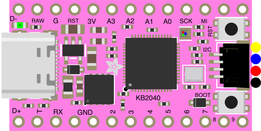
 Design with Adafruit KB2040 in Cirkit Designer
Introduction
The Adafruit KB2040 (Manufacturer Part ID: 5302) is a compact microcontroller board based on the RP2040 chip, designed specifically for keyboard and other input device projects. It features a USB-C interface, multiple GPIO pins, and support for various peripherals. The KB2040 is programmable using CircuitPython, MicroPython, or C/C++, making it versatile for both beginners and advanced users.
Explore Projects Built with Adafruit KB2040
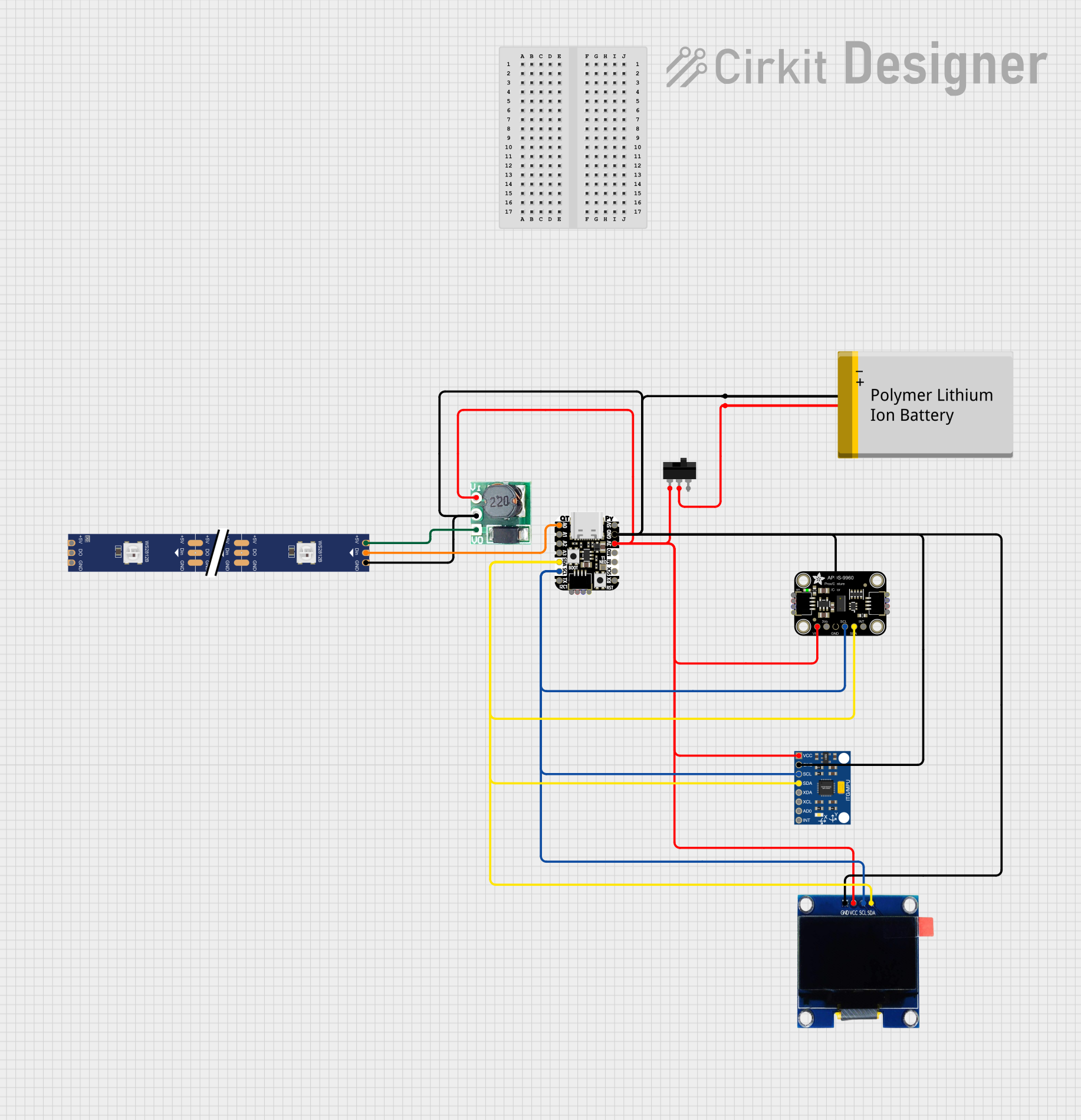 Open Project in Cirkit Designer
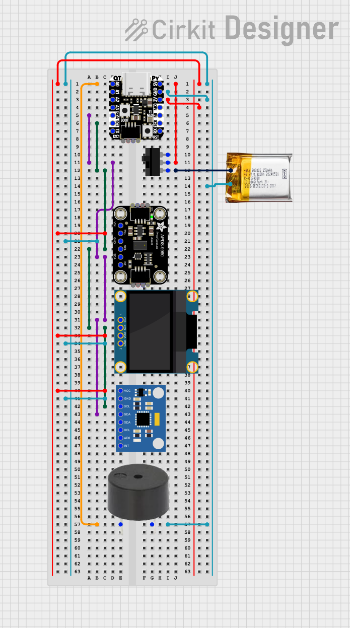 Open Project in Cirkit Designer
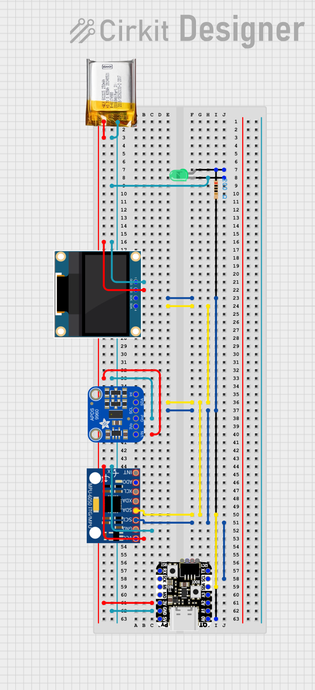 Open Project in Cirkit Designer
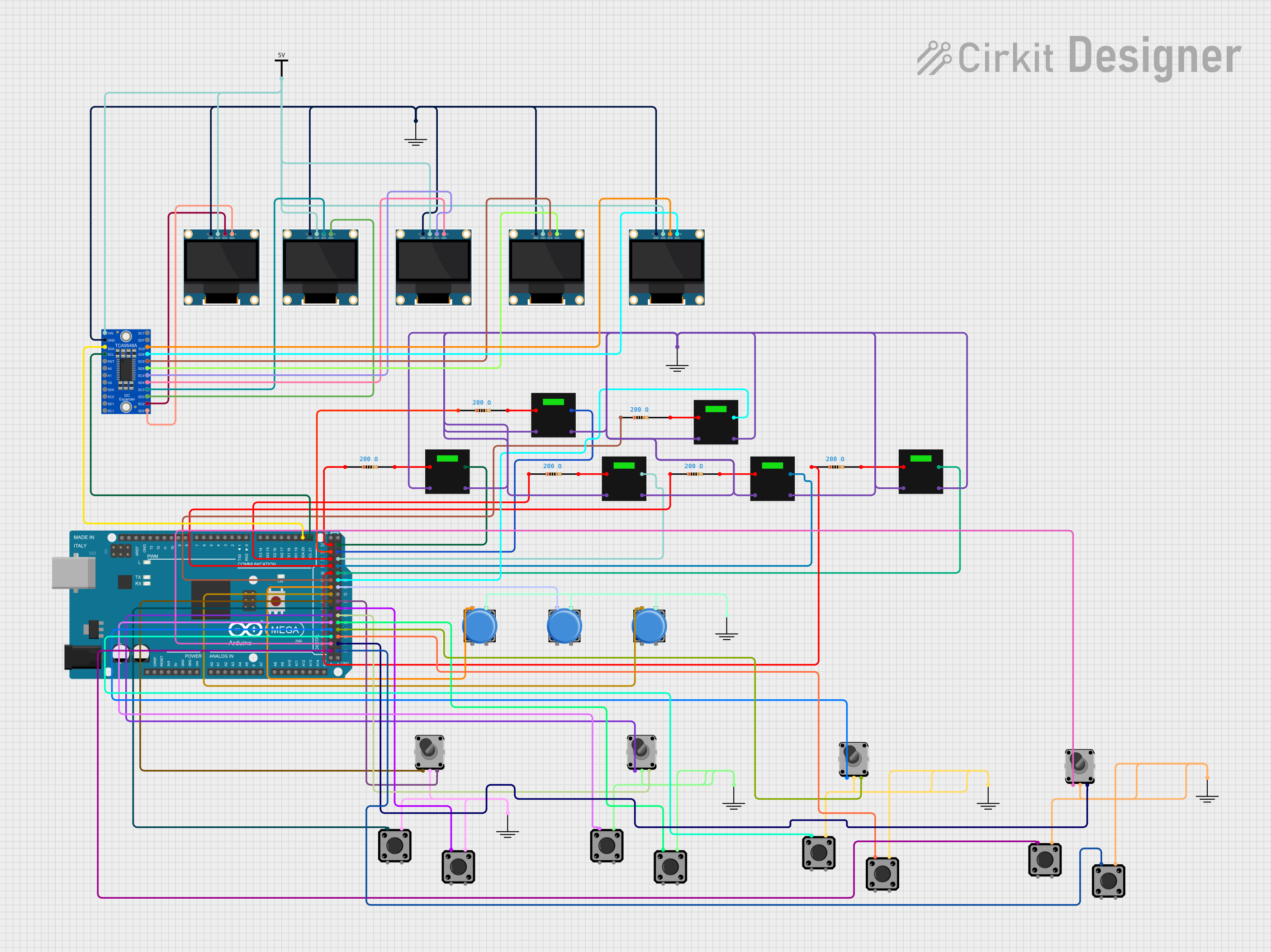 Open Project in Cirkit Designer
Explore Projects Built with Adafruit KB2040
Open Project in Cirkit DesignerOpen Project in Cirkit DesignerOpen Project in Cirkit DesignerOpen Project in Cirkit DesignerCommon Applications and Use Cases
- Custom mechanical keyboards
- Input devices such as macro pads or media controllers
- HID (Human Interface Device) projects
- General-purpose microcontroller applications
- Prototyping and educational projects
Technical Specifications
The Adafruit KB2040 is packed with features that make it ideal for compact and efficient designs. Below are its key technical details:
Key Technical Details
- Microcontroller: RP2040 dual-core ARM Cortex-M0+ processor
- Clock Speed: 133 MHz
- Flash Memory: 8 MB (QSPI Flash)
- RAM: 264 KB SRAM
- USB Interface: USB-C connector with native USB 1.1 support
- GPIO Pins: 20 GPIO pins (including 4 analog inputs)
- Power Supply: 5V via USB-C or external power source
- Operating Voltage: 3.3V logic level
- Dimensions: 51mm x 18mm x 4mm
- Weight: 4.2g
Pin Configuration and Descriptions
The KB2040 features a total of 20 GPIO pins, which are broken out to the sides of the board. Below is the pinout description:
| Pin | Name | Function |
|---|---|---|
| 1 | GND | Ground |
| 2 | 3V3 | 3.3V power output |
| 3 | A0 (GP26) | Analog input 0 / GPIO 26 |
| 4 | A1 (GP27) | Analog input 1 / GPIO 27 |
| 5 | A2 (GP28) | Analog input 2 / GPIO 28 |
| 6 | A3 (GP29) | Analog input 3 / GPIO 29 |
| 7 | GP0 | General-purpose I/O pin 0 |
| 8 | GP1 | General-purpose I/O pin 1 |
| 9 | GP2 | General-purpose I/O pin 2 |
| 10 | GP3 | General-purpose I/O pin 3 |
| 11 | GP4 | General-purpose I/O pin 4 |
| 12 | GP5 | General-purpose I/O pin 5 |
| 13 | GP6 | General-purpose I/O pin 6 |
| 14 | GP7 | General-purpose I/O pin 7 |
| 15 | GP8 | General-purpose I/O pin 8 |
| 16 | GP9 | General-purpose I/O pin 9 |
| 17 | GP10 | General-purpose I/O pin 10 |
| 18 | GP11 | General-purpose I/O pin 11 |
| 19 | SDA (GP20) | I2C data line / GPIO 20 |
| 20 | SCL (GP21) | I2C clock line / GPIO 21 |
Usage Instructions
The Adafruit KB2040 is designed to be easy to use for a variety of projects. Below are the steps and best practices for using the board.
How to Use the KB2040 in a Circuit
Powering the Board:
- Connect the KB2040 to your computer or power source using a USB-C cable.
- Alternatively, supply 5V to the USB pin or 3.3V to the 3V3 pin for external power.
Programming the Board:
- Install CircuitPython or MicroPython by following the instructions on the Adafruit website.
- Alternatively, use the Arduino IDE with the RP2040 board package installed for C/C++ programming.
Connecting Peripherals:
- Use the GPIO pins to connect sensors, LEDs, or other peripherals.
- For I2C devices, connect them to the SDA (GP20) and SCL (GP21) pins.
Uploading Code:
- Drag and drop your CircuitPython code onto the KB2040 when it appears as a USB drive.
- For Arduino, upload the code directly via the USB-C connection.
Important Considerations and Best Practices
- Voltage Levels: The GPIO pins operate at 3.3V logic. Avoid connecting 5V signals directly to the pins.
- ESD Protection: Handle the board with care to avoid electrostatic discharge damage.
- Pin Multiplexing: Some pins have multiple functions (e.g., analog input, I2C, or GPIO). Check the datasheet to avoid conflicts.
- Bootloader Mode: To enter bootloader mode, hold down the BOOT button while connecting the board to your computer.
Example Code for Arduino UNO Integration
Below is an example of using the KB2040 to control an LED:
// Example: Blink an LED connected to GPIO 5 (GP5)

// Define the GPIO pin for the LED
#define LED_PIN 5

void setup() {
  pinMode(LED_PIN, OUTPUT); // Set GPIO 5 as an output
}

void loop() {
  digitalWrite(LED_PIN, HIGH); // Turn the LED on
  delay(1000);                 // Wait for 1 second
  digitalWrite(LED_PIN, LOW);  // Turn the LED off
  delay(1000);                 // Wait for 1 second
}
Troubleshooting and FAQs
Common Issues and Solutions
Board Not Recognized by Computer:
- Ensure the USB-C cable is a data cable, not a charge-only cable.
- Check that the board is in bootloader mode by holding the BOOT button while connecting it.
Code Not Running:
- Verify that the correct firmware (CircuitPython, MicroPython, or Arduino) is installed.
- Check for syntax errors in your code.
GPIO Pins Not Responding:
- Confirm that the pins are configured correctly in your code.
- Ensure that the connected peripherals are functioning and powered properly.
Overheating or Power Issues:
- Avoid drawing excessive current from the GPIO pins.
- Use an external power source if your peripherals require more power than the USB can provide.
FAQs
Can I use the KB2040 for non-keyboard projects?
Yes, the KB2040 is a general-purpose microcontroller and can be used for a wide range of applications.What programming languages are supported?
The KB2040 supports CircuitPython, MicroPython, and C/C++ (via the Arduino IDE or other development environments).How do I reset the board?
Press the RESET button on the board to restart it. To enter bootloader mode, hold the BOOT button while pressing RESET.What is the maximum current output of the GPIO pins?
Each GPIO pin can source or sink up to 12 mA. For higher currents, use an external transistor or driver circuit.
This concludes the documentation for the Adafruit KB2040. For additional resources, visit the Adafruit KB2040 product page.