How to Use PZEM 015 DISPLAY: Examples, Pinouts, and Specs

Introduction
The PZEM 015 is a digital power meter display designed for real-time monitoring of electrical parameters in AC circuits. It measures voltage, current, power, energy, and frequency, making it an essential tool for energy management systems, industrial automation, and home energy monitoring. Its compact design and ease of integration make it suitable for a wide range of applications, including renewable energy systems, power distribution panels, and electrical testing setups.
Explore Projects Built with PZEM 015 DISPLAY


Explore Projects Built with PZEM 015 DISPLAY
Technical Specifications
The PZEM 015 is a versatile and reliable component with the following key specifications:
| Parameter | Specification |
|---|---|
| Voltage Range | 80V - 260V AC |
| Current Range | 0A - 100A (with external current transformer) |
| Power Range | 0W - 22kW |
| Energy Range | 0kWh - 9999kWh |
| Frequency Range | 45Hz - 65Hz |
| Accuracy | ±1% |
| Display Type | LCD with backlight |
| Communication Interface | None (standalone display) |
| Operating Temperature | -10°C to 50°C |
| Dimensions | 79mm x 43mm x 48mm |
Pin Configuration and Descriptions
The PZEM 015 has a simple wiring interface for connecting to the AC circuit and the external current transformer (CT). Below is the pin configuration:
| Pin Name | Description |
|---|---|
| L (Live) | Connect to the live wire of the AC circuit |
| N (Neutral) | Connect to the neutral wire of the AC circuit |
| CT+ | Connect to the positive terminal of the current transformer |
| CT- | Connect to the negative terminal of the current transformer |
Usage Instructions
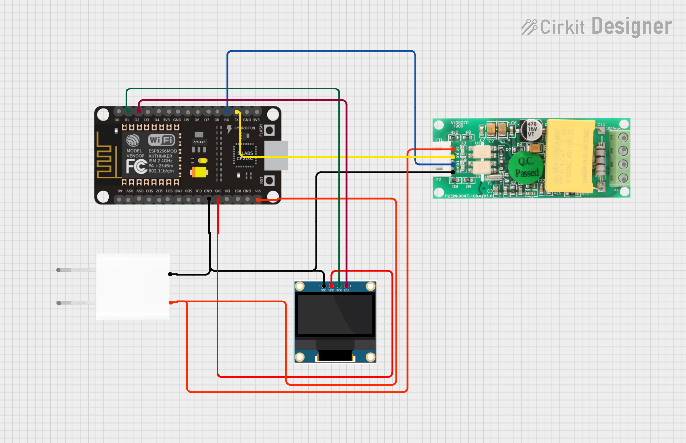
How to Use the PZEM 015 in a Circuit
Wiring the Component:
- Connect the
LandNterminals of the PZEM 015 to the live and neutral wires of the AC circuit, respectively. - Attach the external current transformer (CT) to the
CT+andCT-terminals. Ensure the CT is clamped around the live wire of the circuit to measure current accurately. - Mount the PZEM 015 display in a visible location for easy monitoring.
- Connect the
Powering the Device:
- The PZEM 015 is powered directly from the AC circuit it is monitoring. No additional power supply is required.
Reading Measurements:
- Once powered, the LCD display will show real-time values for voltage, current, power, energy, and frequency.
- Use the button on the display (if available) to cycle through different parameters or reset energy readings.
Important Considerations and Best Practices
- Safety First: Always ensure the circuit is powered off before wiring the PZEM 015 to avoid electric shock or damage to the device.
- Current Transformer Placement: The CT must be clamped around the live wire only. Clamping it around both live and neutral wires will result in incorrect readings.
- Voltage Range: Ensure the monitored circuit operates within the specified voltage range (80V - 260V AC) to prevent damage to the PZEM 015.
- Environmental Conditions: Avoid exposing the device to extreme temperatures, humidity, or direct sunlight to maintain accuracy and longevity.
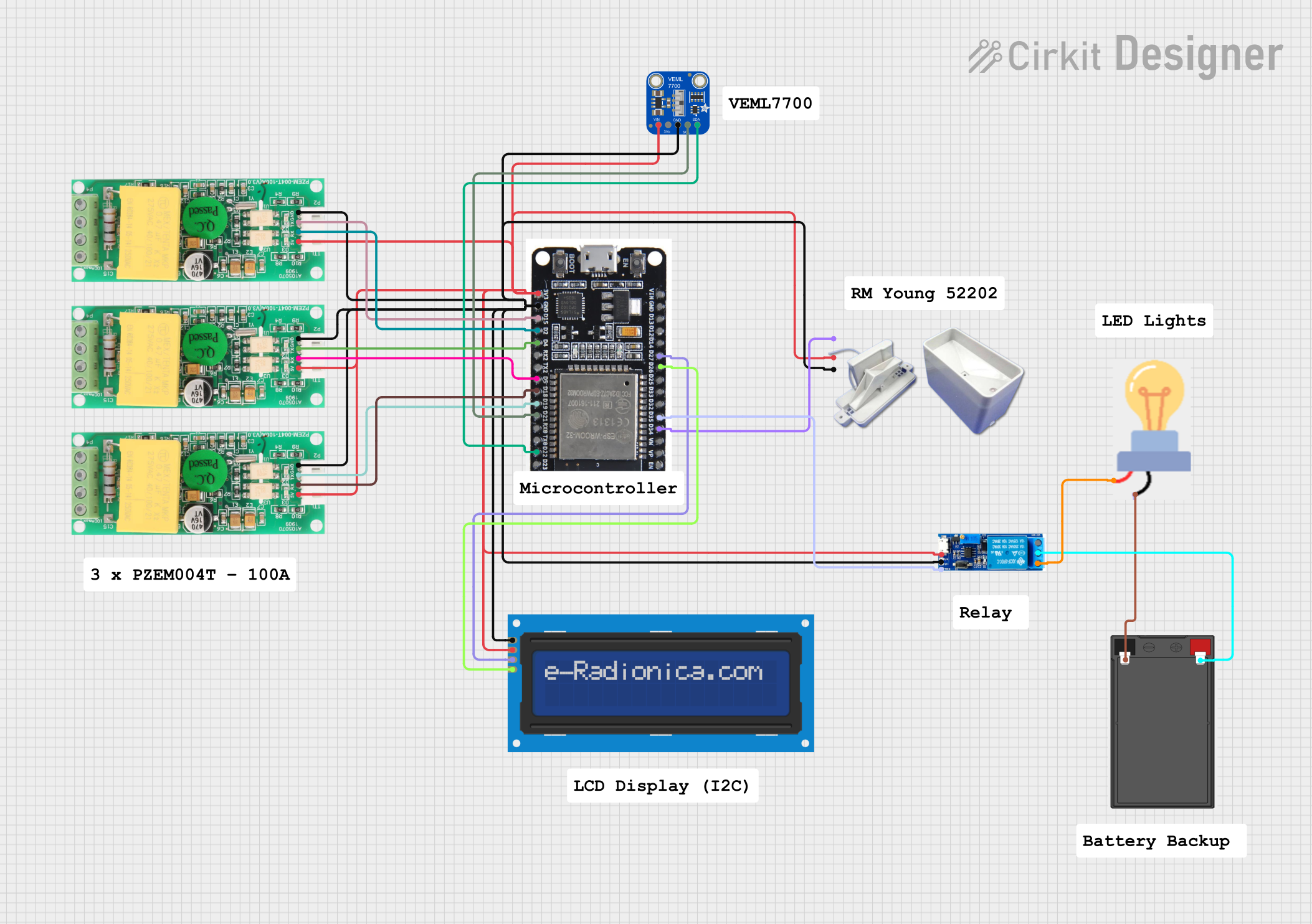
Arduino Integration
Although the PZEM 015 is primarily a standalone display, it can be used with an Arduino UNO for advanced monitoring by interfacing with a compatible PZEM module (e.g., PZEM-004T). Below is an example Arduino code snippet for reading data from a PZEM module:
#include <SoftwareSerial.h>
#include <PZEM004Tv30.h>

// Define RX and TX pins for communication with the PZEM module
SoftwareSerial pzemSerial(10, 11); // RX = pin 10, TX = pin 11
PZEM004Tv30 pzem(&pzemSerial);

void setup() {
  Serial.begin(9600); // Initialize serial monitor
  Serial.println("PZEM Monitoring Started");
}

void loop() {
  float voltage = pzem.voltage(); // Read voltage
  float current = pzem.current(); // Read current
  float power = pzem.power();     // Read power
  float energy = pzem.energy();   // Read energy

  // Print readings to the serial monitor
  Serial.print("Voltage: "); Serial.print(voltage); Serial.println(" V");
  Serial.print("Current: "); Serial.print(current); Serial.println(" A");
  Serial.print("Power: "); Serial.print(power); Serial.println(" W");
  Serial.print("Energy: "); Serial.print(energy); Serial.println(" kWh");
  Serial.println("-----------------------------");

  delay(1000); // Wait 1 second before the next reading
}
Note: The above code is for a PZEM module with UART communication (e.g., PZEM-004T). The PZEM 015 does not have a communication interface and is used as a standalone display.
Troubleshooting and FAQs
Common Issues and Solutions
No Display or Incorrect Readings:
- Cause: Improper wiring or insufficient voltage.
- Solution: Double-check the wiring connections and ensure the monitored circuit is within the voltage range (80V - 260V AC).
Current Reading is Zero:
- Cause: The current transformer (CT) is not properly connected or clamped.
- Solution: Verify the CT connections to the
CT+andCT-terminals. Ensure the CT is clamped around the live wire only.
Energy Reading Does Not Reset:
- Cause: The reset button (if available) is not functioning.
- Solution: Refer to the user manual for the correct reset procedure or check for physical damage to the button.
Flickering Display:
- Cause: Unstable power supply or electrical noise in the circuit.
- Solution: Use a voltage stabilizer or filter to ensure a stable power supply.
FAQs
Can the PZEM 015 measure DC circuits? No, the PZEM 015 is designed specifically for AC circuits and cannot measure DC parameters.
Is the PZEM 015 compatible with microcontrollers like Arduino? The PZEM 015 is a standalone display and does not have a communication interface. For Arduino integration, consider using a PZEM module with UART or Modbus support.
How do I reset the energy reading? If the PZEM 015 has a reset button, press and hold it for a few seconds to reset the energy reading. Refer to the user manual for detailed instructions.
Can I use the PZEM 015 for three-phase systems? No, the PZEM 015 is designed for single-phase AC systems only. For three-phase systems, use a dedicated three-phase power meter.
By following this documentation, users can effectively utilize the PZEM 015 for accurate and reliable power monitoring in AC circuits.