How to Use OLED: Examples, Pinouts, and Specs
Introduction
An Organic Light Emitting Diode (OLED) is a type of display technology that uses organic compounds to emit light when an electric current is applied. Unlike traditional LCDs, OLEDs do not require a backlight, allowing for thinner, more energy-efficient displays. OLEDs are known for their high contrast ratios, vibrant colors, and ability to produce deep blacks, making them ideal for applications requiring high-quality visuals.
Explore Projects Built with OLED


Explore Projects Built with OLED
Common Applications and Use Cases
- Displays for smartphones, tablets, and televisions
- Wearable devices such as smartwatches
- Industrial and medical equipment displays
- DIY electronics projects and prototyping
- Low-power graphical interfaces for embedded systems
Technical Specifications
Below are the general technical specifications for a typical 0.96-inch monochrome OLED display module (commonly used in DIY projects):
| Parameter | Specification |
|---|---|
| Display Type | OLED (Organic Light Emitting Diode) |
| Resolution | 128 x 64 pixels |
| Interface | I2C or SPI |
| Operating Voltage | 3.3V - 5V |
| Operating Current | ~20mA |
| Viewing Angle | >160° |
| Pixel Color | Monochrome (White, Blue, or Yellow) |
| Dimensions | ~27mm x 27mm x 4mm |
Pin Configuration and Descriptions
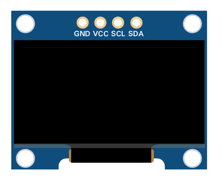
The pinout for a typical 4-pin I2C OLED module is as follows:
| Pin | Name | Description |
|---|---|---|
| 1 | GND | Ground connection |
| 2 | VCC | Power supply (3.3V or 5V) |
| 3 | SCL | Serial Clock Line for I2C communication |
| 4 | SDA | Serial Data Line for I2C communication |
For SPI-based OLED modules, additional pins such as CS (Chip Select) and DC (Data/Command) may be present.
Usage Instructions
How to Use the OLED in a Circuit
- Power the OLED Module: Connect the
VCCpin to a 3.3V or 5V power source and theGNDpin to ground. - Connect Communication Lines:
- For I2C: Connect the
SCLpin to the microcontroller's clock line and theSDApin to the data line. - For SPI: Connect the
CS,DC, andSCLKpins to the respective SPI pins on the microcontroller.
- For I2C: Connect the
- Install Required Libraries: If using an Arduino, install the
Adafruit_SSD1306andAdafruit_GFXlibraries via the Arduino Library Manager. - Write Code: Use the libraries to initialize the display and send data to it.
Important Considerations and Best Practices
- Voltage Compatibility: Ensure the OLED module's operating voltage matches your microcontroller's logic level (3.3V or 5V).
- I2C Address: Most OLED modules have a default I2C address of
0x3Cor0x3D. Check your module's datasheet or documentation. - Avoid Burn-In: Prolonged display of static images can cause burn-in. Use screen savers or periodically refresh the display content.
- Handle with Care: OLED displays are fragile. Avoid applying excessive pressure to the screen.
Example Code for Arduino UNO
Below is an example of how to use a 128x64 I2C OLED with an Arduino UNO:
#include <Wire.h>
#include <Adafruit_GFX.h>
#include <Adafruit_SSD1306.h>

// Define OLED display dimensions
#define SCREEN_WIDTH 128
#define SCREEN_HEIGHT 64

// Create an SSD1306 display object
Adafruit_SSD1306 display(SCREEN_WIDTH, SCREEN_HEIGHT, &Wire, -1);

void setup() {
  // Initialize serial communication for debugging
  Serial.begin(9600);

  // Initialize the OLED display
  if (!display.begin(SSD1306_I2C_ADDRESS, 0x3C)) {
    Serial.println(F("SSD1306 allocation failed"));
    while (true); // Halt execution if initialization fails
  }

  // Clear the display buffer
  display.clearDisplay();

  // Display a welcome message
  display.setTextSize(1); // Set text size
  display.setTextColor(SSD1306_WHITE); // Set text color
  display.setCursor(0, 0); // Set cursor position
  display.println(F("Hello, OLED!")); // Print text
  display.display(); // Update the display
  delay(2000); // Wait for 2 seconds
}

void loop() {
  // Example: Draw a rectangle on the display
  display.clearDisplay(); // Clear the display buffer
  display.drawRect(10, 10, 50, 30, SSD1306_WHITE); // Draw a rectangle
  display.display(); // Update the display
  delay(1000); // Wait for 1 second
}
Troubleshooting and FAQs
Common Issues and Solutions
OLED Display Not Turning On:
- Verify the power connections (
VCCandGND). - Ensure the correct operating voltage (3.3V or 5V) is supplied.
- Check for loose or incorrect wiring.
- Verify the power connections (
No Output on the Display:
- Confirm the I2C address matches the one in your code (default is
0x3C). - Ensure the
Adafruit_SSD1306andAdafruit_GFXlibraries are installed and up to date. - Check the
SCLandSDAconnections for proper communication.
- Confirm the I2C address matches the one in your code (default is
Flickering or Unstable Display:
- Use shorter wires to reduce noise in the I2C or SPI lines.
- Add pull-up resistors (4.7kΩ to 10kΩ) to the
SCLandSDAlines if not already present.
Burn-In or Image Retention:
- Avoid displaying static images for extended periods.
- Use animations or periodically refresh the display content.
FAQs
Q: Can I use the OLED with a Raspberry Pi?
A: Yes, OLED modules are compatible with Raspberry Pi. Use the I2C or SPI interface and install the appropriate libraries (e.g., luma.oled for Python).
Q: How do I change the I2C address of my OLED?
A: Some OLED modules allow changing the I2C address by soldering jumpers on the back of the module. Refer to the module's datasheet for instructions.
Q: Can I use the OLED with 5V logic microcontrollers?
A: Yes, most OLED modules are designed to work with both 3.3V and 5V logic levels. Check your module's specifications to confirm.
Q: What is the lifespan of an OLED display?
A: The typical lifespan of an OLED display is around 10,000 to 50,000 hours, depending on usage and brightness settings.