How to Use 5V Step-Up/Step-Down Voltage Regulator S7V7F5: Examples, Pinouts, and Specs
Introduction
The 5V Step-Up/Step-Down Voltage Regulator S7V7F5 (Pololu part #2119) is a versatile DC-DC converter designed to provide a stable 5V output from a wide range of input voltages. This regulator can seamlessly step up or step down the input voltage, making it ideal for applications where the input voltage may fluctuate above or below 5V. Its compact size and efficiency make it suitable for battery-powered devices, microcontroller projects, and portable electronics.
Explore Projects Built with 5V Step-Up/Step-Down Voltage Regulator S7V7F5


Explore Projects Built with 5V Step-Up/Step-Down Voltage Regulator S7V7F5
Common Applications
- Powering 5V microcontrollers (e.g., Arduino, Raspberry Pi Pico)
- Battery-powered devices with varying input voltages
- Portable electronics requiring a stable 5V supply
- Robotics and embedded systems
Technical Specifications
The following table outlines the key technical details of the S7V7F5 voltage regulator:
| Parameter | Value |
|---|---|
| Output Voltage | 5V (regulated) |
| Input Voltage Range | 2.7V to 11.8V |
| Maximum Output Current | 1A (typical, depends on input voltage) |
| Efficiency | Up to 90% (varies with input/output load) |
| Quiescent Current | ~0.2 mA (typical) |
| Dimensions | 0.35" × 0.475" × 0.1" (9 mm × 12 mm × 3 mm) |
| Weight | 0.5 g |
Pin Configuration and Descriptions
The S7V7F5 regulator has six pins, as described in the table below:
| Pin | Name | Description |
|---|---|---|
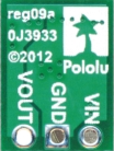
| 1 | VIN | Input voltage (2.7V to 11.8V). Connect to the positive terminal of the power source. |
| 2 | GND | Ground. Connect to the negative terminal of the power source. |
| 3 | VOUT | Regulated 5V output. Connect to the load requiring 5V. |
| 4 | GND | Ground. Additional ground pin for improved connection. |
| 5 | SHDN | Shutdown pin. Drive low to disable the regulator; leave floating or high to enable. |
| 6 | GND | Ground. Additional ground pin for improved connection. |
Usage Instructions
How to Use the Component in a Circuit
Connect the Input Voltage (VIN):
Attach the positive terminal of your power source (e.g., battery or power supply) to the VIN pin. Ensure the input voltage is within the range of 2.7V to 11.8V.Connect the Ground (GND):
Connect the negative terminal of your power source to any of the GND pins on the regulator.Connect the Output Voltage (VOUT):
Attach the VOUT pin to the positive terminal of your load (e.g., microcontroller, sensor, or other 5V device).Optional - Use the SHDN Pin:
If you want to control the regulator's operation, connect the SHDN pin to a microcontroller or switch. Drive it low to disable the regulator or leave it floating/high to enable it.Verify Connections:
Double-check all connections to ensure proper polarity and secure wiring.Power On:
Turn on the power source. The regulator will automatically adjust the input voltage to provide a stable 5V output.
Important Considerations and Best Practices
- Input Voltage Range: Ensure the input voltage stays within the specified range (2.7V to 11.8V) to avoid damaging the regulator.
- Heat Dissipation: While the regulator is efficient, it may generate heat under high loads. Ensure adequate ventilation or heat sinking if operating near the maximum current.
- Capacitors: For optimal performance, consider adding input and output capacitors (e.g., 10 µF ceramic capacitors) close to the regulator to reduce noise and improve stability.
- Load Requirements: The maximum output current depends on the input voltage. For example, at lower input voltages, the regulator may not provide the full 1A output.
Example: Using with an Arduino UNO
The S7V7F5 can be used to power an Arduino UNO from a 3.7V LiPo battery. Below is an example circuit and Arduino code to toggle the SHDN pin:
Circuit Connections
- Connect the LiPo battery's positive terminal to VIN and negative terminal to GND.
- Connect the VOUT pin to the Arduino's 5V pin.
- Connect one of the GND pins to the Arduino's GND pin.
- Connect the SHDN pin to Arduino digital pin 7.
Arduino Code
// Example code to control the SHDN pin of the S7V7F5 regulator
const int shutdownPin = 7; // Pin connected to SHDN

void setup() {
  pinMode(shutdownPin, OUTPUT); // Set SHDN pin as output
  digitalWrite(shutdownPin, HIGH); // Enable the regulator
}

void loop() {
  // Toggle the regulator on and off every 5 seconds
  digitalWrite(shutdownPin, LOW); // Disable the regulator
  delay(5000); // Wait for 5 seconds
  digitalWrite(shutdownPin, HIGH); // Enable the regulator
  delay(5000); // Wait for 5 seconds
}
Troubleshooting and FAQs
Common Issues and Solutions
No Output Voltage:
- Cause: Incorrect wiring or insufficient input voltage.
- Solution: Verify all connections and ensure the input voltage is within the specified range.
Regulator Overheating:
- Cause: Excessive load or poor ventilation.
- Solution: Reduce the load current or improve heat dissipation with a heatsink or airflow.
Output Voltage Fluctuations:
- Cause: Insufficient input/output capacitors or noisy power source.
- Solution: Add 10 µF ceramic capacitors close to the VIN and VOUT pins.
SHDN Pin Not Working:
- Cause: Incorrect logic level or floating pin.
- Solution: Ensure the SHDN pin is pulled low to disable or high to enable the regulator.
FAQs
Q: Can I use this regulator to power a Raspberry Pi?
A: The S7V7F5 can provide up to 1A, which may not be sufficient for all Raspberry Pi models. Check your Raspberry Pi's power requirements before using this regulator.
Q: What happens if the input voltage exceeds 11.8V?
A: Exceeding the maximum input voltage can damage the regulator. Use a voltage limiter or ensure your power source stays within the specified range.
Q: Can I leave the SHDN pin floating?
A: Yes, the SHDN pin can be left floating, as it is internally pulled high to enable the regulator by default.