How to Use SPEEDYBEE F405 WING PDB Board Front: Examples, Pinouts, and Specs
Introduction
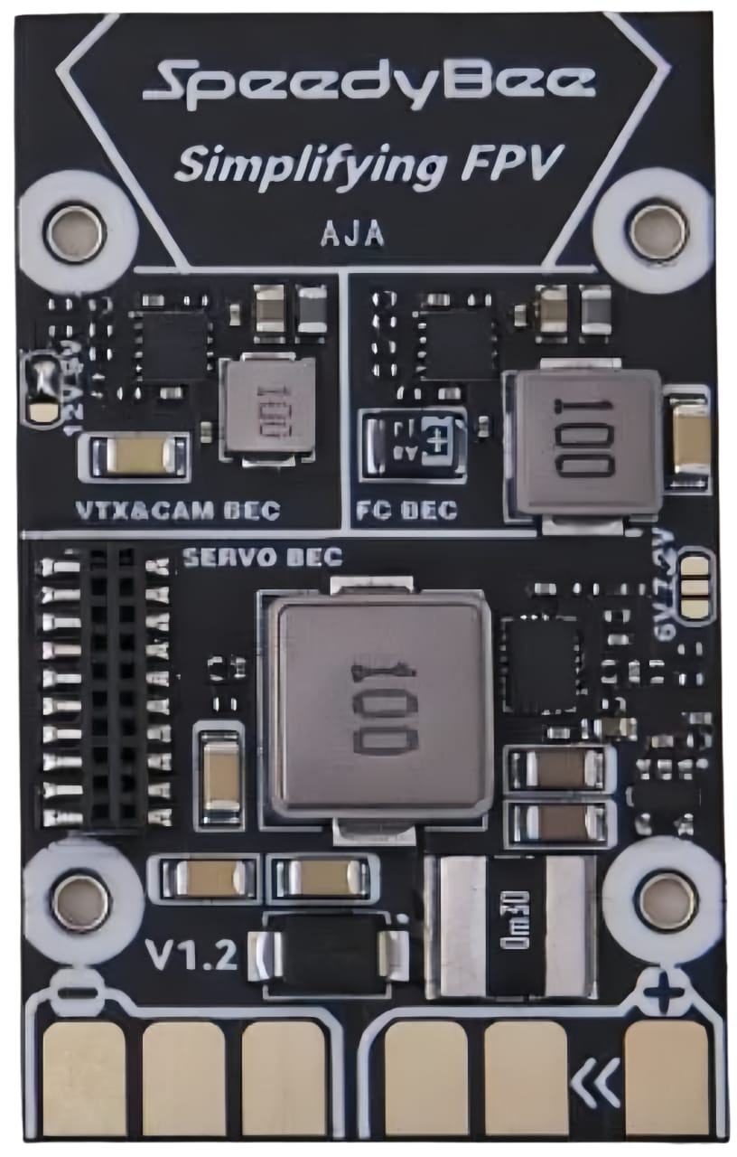
The SPEEDYBEE F405 WING PDB Board Front is a versatile power distribution board (PDB) designed specifically for drone applications. It integrates an F405 flight controller, offering efficient power management and seamless connectivity for various drone components such as motors, ESCs (Electronic Speed Controllers), GPS modules, and FPV (First-Person View) systems. This board is ideal for fixed-wing drones and other UAVs requiring a compact, all-in-one solution for power distribution and flight control.
Explore Projects Built with SPEEDYBEE F405 WING PDB Board Front


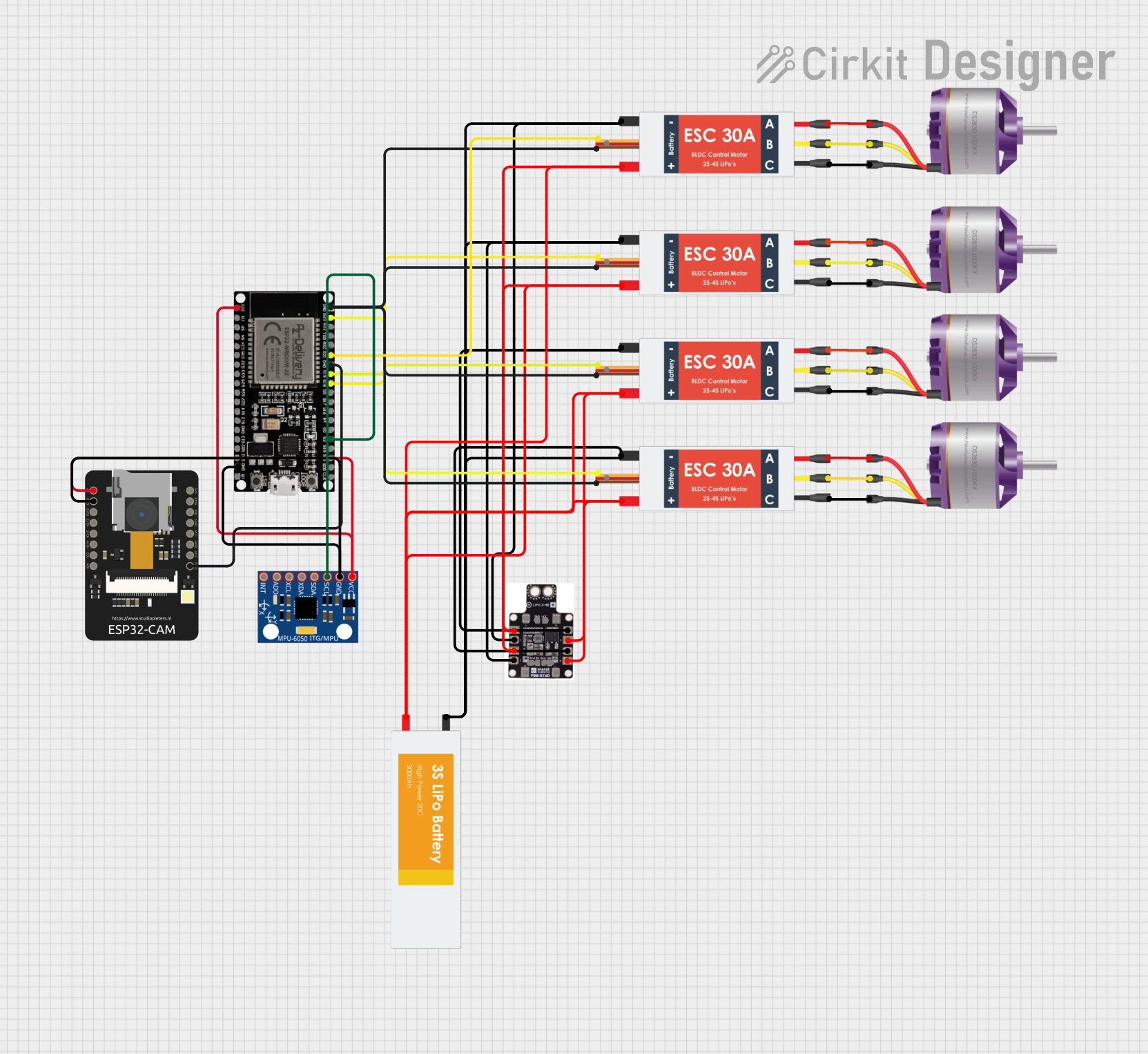
Explore Projects Built with SPEEDYBEE F405 WING PDB Board Front
Common Applications and Use Cases
- Fixed-wing drones and UAVs
- FPV (First-Person View) racing drones
- Long-range drones with GPS and telemetry systems
- Applications requiring efficient power distribution and flight control integration
Technical Specifications
The SPEEDYBEE F405 WING PDB Board Front is packed with features to support a wide range of drone configurations. Below are the key technical details:
Key Technical Details
- Processor: STM32F405 microcontroller
- Input Voltage Range: 7V to 42V (2S to 10S LiPo batteries)
- BEC Output:
- 5V @ 3A
- 9V @ 3A
- Current Sensor: Integrated, supports up to 200A
- UART Ports: 6 UARTs for peripherals (e.g., GPS, telemetry, receivers)
- ESC Signal Output: 8 PWM outputs
- Onboard OSD: Integrated Betaflight OSD
- Connectivity: Wi-Fi module for wireless configuration
- Dimensions: 68mm x 50mm
- Weight: 15g
Pin Configuration and Descriptions
The SPEEDYBEE F405 WING PDB Board Front features multiple pins for connecting various components. Below is the pinout description:
| Pin Name | Description |
|---|---|
| GND | Ground connection for power and signal |
| VBAT | Battery voltage input (7V to 42V) |
| 5V | 5V output for powering peripherals |
| 9V | 9V output for FPV cameras or VTX modules |
| PWM1-8 | PWM signal outputs for ESCs or servos |
| UART1-TX/RX | UART1 for GPS or telemetry modules |
| UART2-TX/RX | UART2 for receivers or other peripherals |
| UART3-TX/RX | UART3 for additional peripherals |
| CURR | Current sensor output for monitoring power consumption |
| RSSI | Analog input for receiver signal strength indication |
| LED | Addressable LED signal output |
| Buzzer | Buzzer signal output for audible alerts |
Usage Instructions
The SPEEDYBEE F405 WING PDB Board Front is designed for easy integration into drone systems. Follow the steps below to use the board effectively:
Step 1: Power Connection
- Connect the battery to the VBAT and GND pins. Ensure the voltage is within the supported range (7V to 42V).
- Use the onboard BEC outputs (5V or 9V) to power peripherals such as FPV cameras, VTX modules, or receivers.
Step 2: Connecting ESCs and Motors
- Connect the signal wires of your ESCs to the PWM1-8 pins.
- Ensure the ESCs are properly calibrated and configured for your drone's motor setup.
Step 3: Peripheral Connections
- Connect GPS modules, telemetry devices, or receivers to the appropriate UART ports.
- Use the RSSI pin for analog signal strength monitoring if supported by your receiver.
Step 4: Configuring the Flight Controller
- Use the integrated Wi-Fi module to wirelessly configure the flight controller via the SpeedyBee app or Betaflight Configurator.
- Set up the OSD, PID tuning, and other flight parameters as needed.
Step 5: Testing and Calibration
- Perform a pre-flight check to ensure all connections are secure and components are functioning correctly.
- Calibrate the accelerometer, compass, and ESCs before the first flight.
Arduino UNO Integration Example
While the SPEEDYBEE F405 WING PDB Board Front is not typically used with an Arduino UNO, you can use the UART ports to communicate with an Arduino for custom applications. Below is an example code snippet for reading telemetry data via UART:
#include <SoftwareSerial.h>

// Define RX and TX pins for UART communication
#define RX_PIN 10
#define TX_PIN 11

// Initialize SoftwareSerial for UART communication
SoftwareSerial telemetrySerial(RX_PIN, TX_PIN);

void setup() {
  // Start serial communication with the telemetry module
  telemetrySerial.begin(9600);
  Serial.begin(9600); // For debugging via the Serial Monitor

  Serial.println("Telemetry communication initialized.");
}

void loop() {
  // Check if data is available from the telemetry module
  if (telemetrySerial.available()) {
    String telemetryData = telemetrySerial.readString();
    Serial.println("Telemetry Data: " + telemetryData);
  }

  delay(100); // Small delay to avoid overwhelming the serial buffer
}
Important Considerations and Best Practices
- Ensure the battery voltage does not exceed the board's maximum input voltage (42V).
- Use appropriate wire gauges for power connections to handle high currents safely.
- Secure all connections with solder or connectors to prevent disconnections during flight.
- Regularly inspect the board for damage or wear, especially after crashes.
Troubleshooting and FAQs
Common Issues and Solutions
Board Not Powering On
- Check the battery connection and ensure the voltage is within the supported range.
- Verify that the solder joints on the power pads are secure.
No Signal to ESCs
- Ensure the ESC signal wires are connected to the correct PWM pins.
- Verify that the flight controller firmware is configured correctly for your motor setup.
Wi-Fi Module Not Connecting
- Ensure the board is powered and the Wi-Fi module is enabled in the firmware.
- Reset the Wi-Fi module and try reconnecting using the SpeedyBee app.
OSD Not Displaying
- Check the connection between the flight controller and the FPV camera/VTX.
- Ensure the OSD settings are enabled in the Betaflight Configurator.
FAQs
Can I use this board with a 12S LiPo battery? No, the maximum supported input voltage is 42V, which corresponds to a 10S LiPo battery.
Does the board support iNAV firmware? Yes, the SPEEDYBEE F405 WING PDB Board Front is compatible with both Betaflight and iNAV firmware.
How do I update the firmware? Use the SpeedyBee app or Betaflight Configurator to flash the latest firmware via USB or Wi-Fi.
Can I connect multiple GPS modules? Yes, you can connect multiple GPS modules to different UART ports, but ensure the firmware supports this configuration.
By following this documentation, you can effectively integrate and operate the SPEEDYBEE F405 WING PDB Board Front in your drone projects.