
How to Use Fan: Examples, Pinouts, and Specs
 Design with Fan in Cirkit Designer
Introduction
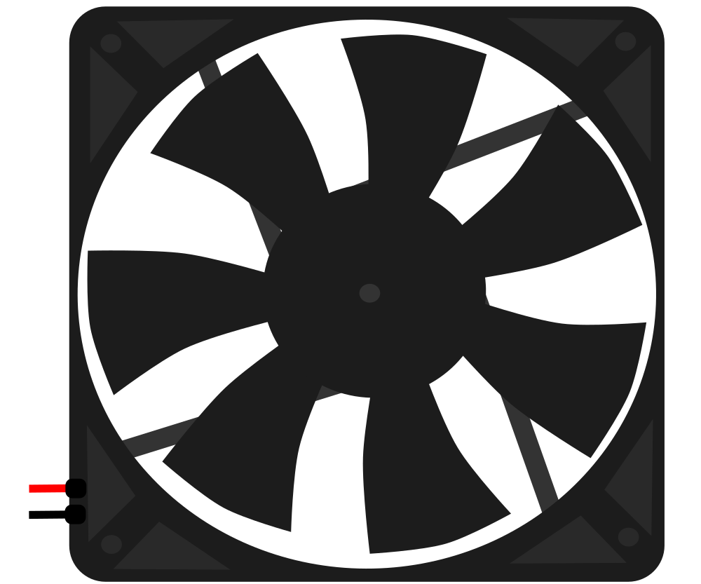
A fan is a device that creates airflow by rotating blades, commonly used for cooling or ventilation in electronic circuits and systems. It is an essential component in thermal management, helping to dissipate heat generated by electronic components such as processors, power supplies, and other heat-sensitive devices. Fans are available in various sizes, voltages, and configurations to suit different applications.
Explore Projects Built with Fan
 Open Project in Cirkit Designer
 Open Project in Cirkit Designer
 Open Project in Cirkit Designer
 Open Project in Cirkit Designer
Explore Projects Built with Fan
Open Project in Cirkit DesignerOpen Project in Cirkit DesignerOpen Project in Cirkit DesignerOpen Project in Cirkit DesignerCommon Applications and Use Cases
- Cooling computer processors, GPUs, and power supplies
- Ventilation in enclosures and cabinets
- Heat dissipation in industrial equipment
- Airflow management in HVAC systems
- Cooling for 3D printers and other hobbyist projects
Technical Specifications
Below are the general technical specifications for a typical DC fan used in electronic applications. Specifications may vary depending on the specific model.
Key Technical Details
- Operating Voltage: 5V, 12V, or 24V DC (common variants)
- Current Consumption: 0.1A to 0.5A (depending on size and voltage)
- Power Rating: 0.5W to 5W
- Speed: 1000 to 5000 RPM (Revolutions Per Minute)
- Airflow: 10 to 100 CFM (Cubic Feet per Minute)
- Noise Level: 20 to 40 dBA
- Connector Type: 2-pin, 3-pin, or 4-pin
- Bearing Type: Sleeve bearing or ball bearing
- Dimensions: Common sizes include 40mm, 60mm, 80mm, 120mm, and 140mm
Pin Configuration and Descriptions
The pin configuration depends on the type of fan (2-pin, 3-pin, or 4-pin). Below are the details:
2-Pin Fan
| Pin Number | Name | Description |
|---|---|---|
| 1 | VCC | Positive power supply (e.g., 12V DC) |
| 2 | GND | Ground connection |
3-Pin Fan
| Pin Number | Name | Description |
|---|---|---|
| 1 | VCC | Positive power supply (e.g., 12V DC) |
| 2 | GND | Ground connection |
| 3 | Tachometer | Outputs a signal for speed monitoring |
4-Pin Fan
| Pin Number | Name | Description |
|---|---|---|
| 1 | VCC | Positive power supply (e.g., 12V DC) |
| 2 | GND | Ground connection |
| 3 | Tachometer | Outputs a signal for speed monitoring |
| 4 | PWM | Pulse Width Modulation for speed control |
Usage Instructions
How to Use the Fan in a Circuit
- Power Connection: Connect the VCC pin to the appropriate voltage source (e.g., 12V DC) and the GND pin to the ground of the circuit.
- Speed Control (Optional): For 4-pin fans, use a PWM signal on the PWM pin to control the fan speed. A typical PWM frequency is 25 kHz.
- Monitoring (Optional): For 3-pin and 4-pin fans, connect the Tachometer pin to a microcontroller or monitoring circuit to measure the fan's speed.
Important Considerations and Best Practices
- Voltage Compatibility: Ensure the fan's operating voltage matches the power supply in your circuit.
- Current Rating: Verify that the power supply can provide sufficient current for the fan.
- Orientation: Install the fan in the correct orientation to ensure proper airflow direction.
- Noise: Choose a fan with a suitable noise level for your application.
- PWM Signal: When using PWM control, ensure the duty cycle and frequency are within the fan's specifications.
Example: Connecting a 4-Pin Fan to an Arduino UNO
Below is an example of how to control a 4-pin fan using an Arduino UNO and PWM.
// Define the PWM pin for fan control
const int fanPwmPin = 9; // Connect to the PWM pin of the fan

void setup() {
  pinMode(fanPwmPin, OUTPUT); // Set the PWM pin as an output
}

void loop() {
  // Set fan speed to 50% using PWM (128 out of 255)
  analogWrite(fanPwmPin, 128);
  delay(5000); // Run at 50% speed for 5 seconds

  // Set fan speed to 100% using PWM (255 out of 255)
  analogWrite(fanPwmPin, 255);
  delay(5000); // Run at full speed for 5 seconds
}
Troubleshooting and FAQs
Common Issues and Solutions
Fan Does Not Spin
- Cause: Incorrect voltage or loose connections.
- Solution: Verify the power supply voltage and ensure all connections are secure.
Fan Spins Slowly
- Cause: Insufficient power supply or high PWM duty cycle.
- Solution: Check the power supply's current rating and adjust the PWM signal.
Excessive Noise
- Cause: Dust buildup or worn-out bearings.
- Solution: Clean the fan blades and consider replacing the fan if the bearings are damaged.
Tachometer Signal Not Detected
- Cause: Incorrect connection or incompatible microcontroller.
- Solution: Verify the tachometer pin connection and ensure the microcontroller can read the signal.
FAQs
Q: Can I use a 12V fan with a 5V power supply?
A: No, a 12V fan requires a 12V power supply to operate correctly. Using a lower voltage may prevent the fan from spinning or reduce its performance.
Q: How do I reverse the airflow direction?
A: You cannot reverse the airflow direction electrically. Instead, physically flip the fan to change the airflow direction.
Q: What is the difference between a 3-pin and a 4-pin fan?
A: A 3-pin fan provides speed monitoring via the tachometer pin, while a 4-pin fan adds PWM control for precise speed adjustment.