How to Use TMC2208: Examples, Pinouts, and Specs
Introduction
The TMC2208 is a high-performance stepper motor driver manufactured by Arduino (Part ID: 1). It is designed to deliver low-noise operation and precise motion control, making it ideal for applications such as 3D printers, CNC machines, and other motion control systems. The TMC2208 supports microstepping, which ensures smooth and accurate motor movements, and features UART communication for easy configuration and real-time monitoring.
Explore Projects Built with TMC2208


Explore Projects Built with TMC2208
Common Applications:
- 3D printers for precise and quiet motor control
- CNC machines for smooth motion and high accuracy
- Robotics and automation systems
- Any application requiring low-noise stepper motor operation
Technical Specifications
The TMC2208 is a versatile and efficient stepper motor driver with the following key specifications:
| Parameter | Value |
|---|---|
| Operating Voltage | 4.75V to 36V |
| Maximum Motor Current | 1.2A RMS (2.0A peak) |
| Microstepping Capability | Up to 256 microsteps per full step |
| Communication Interface | UART |
| Logic Voltage | 3.3V or 5V compatible |
| Standby Current | < 50 µA |
| Operating Temperature | -40°C to +125°C |
| Package Type | QFN28 |
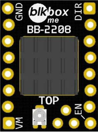
Pin Configuration and Descriptions
The TMC2208 has 28 pins, but the most commonly used pins for basic operation are listed below:
| Pin Name | Pin Number | Description |
|---|---|---|
| VM | 1 | Motor power supply input (4.75V to 36V). |
| GND | 2, 3, 4 | Ground connection. |
| VCC_IO | 5 | Logic voltage input (3.3V or 5V). |
| EN | 6 | Enable pin. Active low to enable the driver. |
| STEP | 7 | Step input for controlling motor steps. |
| DIR | 8 | Direction input for controlling motor rotation direction. |
| UART_TX | 9 | UART transmit pin for communication. |
| UART_RX | 10 | UART receive pin for communication. |
| MS1, MS2 | 11, 12 | Microstepping resolution selection pins. |
| DIAG | 13 | Diagnostic output pin for fault detection. |
| NC | Various | Not connected. Leave unconnected or follow the datasheet for specific details. |
Usage Instructions
How to Use the TMC2208 in a Circuit
- Power Supply: Connect the motor power supply (VM) to a voltage source between 4.75V and 36V. Ensure the power supply can handle the current requirements of your stepper motor.
- Logic Voltage: Provide a 3.3V or 5V logic voltage to the VCC_IO pin.
- Motor Connections: Connect the stepper motor's coils to the appropriate output pins of the TMC2208.
- Control Pins:
- Use the
STEPpin to send pulses for each motor step. - Use the
DIRpin to set the motor's rotation direction.
- Use the
- Microstepping: Configure the microstepping resolution using the MS1 and MS2 pins or via UART.
- UART Communication: Connect the UART_TX and UART_RX pins to a microcontroller for advanced configuration and monitoring.
Important Considerations and Best Practices
- Cooling: The TMC2208 can generate heat during operation. Use a heatsink or active cooling if necessary to prevent overheating.
- Current Limiting: Set the motor current limit appropriately to avoid damaging the motor or driver. This can be configured via UART or by adjusting the reference voltage (VREF).
- Decoupling Capacitors: Place decoupling capacitors (e.g., 100 µF and 0.1 µF) close to the VM and VCC_IO pins to stabilize the power supply.
- Fault Detection: Monitor the DIAG pin for fault conditions such as overtemperature or short circuits.
Example: Using TMC2208 with Arduino UNO
Below is an example of how to control a stepper motor using the TMC2208 and an Arduino UNO:
// Example: Controlling a stepper motor with TMC2208 and Arduino UNO

#define STEP_PIN 3  // Pin connected to the STEP pin of TMC2208
#define DIR_PIN 4   // Pin connected to the DIR pin of TMC2208

void setup() {
  pinMode(STEP_PIN, OUTPUT); // Set STEP pin as output
  pinMode(DIR_PIN, OUTPUT);  // Set DIR pin as output

  digitalWrite(DIR_PIN, LOW); // Set initial direction (LOW = clockwise)
}

void loop() {
  // Generate step pulses to move the motor
  digitalWrite(STEP_PIN, HIGH); // Set STEP pin HIGH
  delayMicroseconds(500);       // Wait for 500 microseconds
  digitalWrite(STEP_PIN, LOW);  // Set STEP pin LOW
  delayMicroseconds(500);       // Wait for 500 microseconds
}
Notes:
- Adjust the
delayMicroseconds()values to control the motor speed. - Use UART communication for advanced features like current control and diagnostics.
Troubleshooting and FAQs
Common Issues and Solutions
Motor Not Moving:
- Check the power supply connections and ensure the voltage is within the specified range.
- Verify the STEP and DIR signals are being sent correctly from the microcontroller.
- Ensure the motor coils are connected to the correct output pins.
Overheating:
- Use a heatsink or active cooling to dissipate heat.
- Reduce the motor current limit via UART or VREF adjustment.
No UART Communication:
- Verify the UART_TX and UART_RX connections between the TMC2208 and the microcontroller.
- Ensure the baud rate matches the TMC2208's default or configured value.
Motor Vibrations or Noise:
- Enable microstepping to reduce vibrations and improve smoothness.
- Check the motor's current limit and adjust if necessary.
FAQs
Q: Can the TMC2208 operate without UART communication?
A: Yes, the TMC2208 can operate in standalone mode using the STEP and DIR pins. However, UART communication is required for advanced configuration and monitoring.
Q: What is the default microstepping resolution?
A: The default resolution is 16 microsteps per full step. This can be increased to 256 microsteps using interpolation or UART configuration.
Q: How do I set the motor current limit?
A: The motor current limit can be set via UART or by adjusting the reference voltage (VREF) using a potentiometer or resistor divider.
Q: Is the TMC2208 compatible with 12V and 24V systems?
A: Yes, the TMC2208 supports a wide voltage range (4.75V to 36V), making it compatible with 12V and 24V systems.
This concludes the documentation for the TMC2208 stepper motor driver. For further details, refer to the official datasheet or Arduino's support resources.