How to Use 3 Selector Switch: Examples, Pinouts, and Specs
Introduction
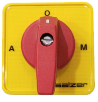
The 3 Selector Switch (Manufacturer: Shopee, Part ID: S1661152-A 16A Poles 2 A-O-M) is an electromechanical device designed to allow users to select one of three different circuits or functions. It features three distinct positions, typically labeled as A, O (Off), and M, enabling control over multiple pathways in a circuit. This switch is commonly used in applications such as lighting control, motor direction selection, and industrial machinery.
Explore Projects Built with 3 Selector Switch


Explore Projects Built with 3 Selector Switch
Common Applications:
- Lighting Control: Switching between different lighting circuits or modes.
- Motor Control: Selecting motor direction (e.g., forward, reverse, or off).
- Industrial Equipment: Controlling multiple operational states of machinery.
- Home Automation: Switching between different power sources or devices.
Technical Specifications
Key Technical Details:
- Manufacturer: Shopee
- Part ID: S1661152-A 16A Poles 2 A-O-M
- Rated Current: 16A
- Rated Voltage: 250V AC
- Number of Positions: 3 (A, O, M)
- Pole Configuration: 2 poles
- Contact Type: Rotary switch with mechanical detents
- Mounting Type: Panel mount
- Material: Flame-retardant plastic housing with metal contacts
- Operating Temperature: -20°C to 70°C
- Durability: 50,000 switching cycles (mechanical)
Pin Configuration and Descriptions:
The 3 Selector Switch typically has six terminals arranged in two rows, corresponding to the two poles. Below is the pin configuration:
| Pin Number | Label | Description |
|---|---|---|
| 1 | A1 | Input for Pole 1 |
| 2 | A2 | Output for Pole 1 (Position A) |
| 3 | O1 | Output for Pole 1 (Position O - Off) |
| 4 | B1 | Input for Pole 2 |
| 5 | B2 | Output for Pole 2 (Position M) |
| 6 | O2 | Output for Pole 2 (Position O - Off) |
Usage Instructions
How to Use the Component in a Circuit:
Wiring the Switch:
- Connect the input terminals (A1 and B1) to the power source or control signal.
- Connect the output terminals (A2, O1, B2, O2) to the respective circuits or devices you wish to control.
- Ensure proper insulation and secure connections to avoid short circuits.
Selecting a Position:
- Rotate the switch to one of the three positions:
- A: Activates the circuit connected to A2.
- O: Disconnects all circuits (Off position).
- M: Activates the circuit connected to B2.
- Rotate the switch to one of the three positions:
Mounting:
- Install the switch into a panel cutout using the provided mounting hardware.
- Ensure the switch is securely fastened to prevent movement during operation.
Important Considerations and Best Practices:
- Current and Voltage Ratings: Do not exceed the rated current (16A) or voltage (250V AC) to avoid damage or hazards.
- Debouncing: If used in digital circuits, consider adding a debounce circuit to prevent false triggering.
- Environmental Conditions: Avoid exposure to moisture, dust, or extreme temperatures beyond the specified range.
- Safety: Always disconnect power before wiring or modifying the circuit.
Example: Using with an Arduino UNO
The 3 Selector Switch can be used with an Arduino UNO to read its position and control devices accordingly. Below is an example code snippet:
// Arduino code to read the position of a 3 Selector Switch
// and control an LED based on the selected position.

const int pinA = 2; // Connect Position A output to digital pin 2
const int pinO = 3; // Connect Position O output to digital pin 3
const int pinM = 4; // Connect Position M output to digital pin 4
const int ledPin = 13; // Built-in LED on Arduino

void setup() {
  pinMode(pinA, INPUT_PULLUP); // Set pinA as input with pull-up resistor
  pinMode(pinO, INPUT_PULLUP); // Set pinO as input with pull-up resistor
  pinMode(pinM, INPUT_PULLUP); // Set pinM as input with pull-up resistor
  pinMode(ledPin, OUTPUT);     // Set LED pin as output
}

void loop() {
  if (digitalRead(pinA) == LOW) {
    // If Position A is selected, turn on the LED
    digitalWrite(ledPin, HIGH);
  } else if (digitalRead(pinM) == LOW) {
    // If Position M is selected, blink the LED
    digitalWrite(ledPin, HIGH);
    delay(500);
    digitalWrite(ledPin, LOW);
    delay(500);
  } else {
    // If Position O (Off) is selected, turn off the LED
    digitalWrite(ledPin, LOW);
  }
}
Troubleshooting and FAQs
Common Issues and Solutions:
Switch Not Functioning:
- Cause: Loose or incorrect wiring.
- Solution: Double-check all connections and ensure proper wiring as per the pin configuration.
Overheating:
- Cause: Exceeding the rated current or voltage.
- Solution: Verify that the connected load does not exceed 16A or 250V AC.
Intermittent Operation:
- Cause: Dirty or worn contacts.
- Solution: Clean the contacts with a contact cleaner or replace the switch if necessary.
Arduino Not Detecting Position:
- Cause: Missing pull-up resistors or incorrect pin connections.
- Solution: Ensure pull-up resistors are enabled in the code and verify connections.
FAQs:
Q: Can this switch be used for DC circuits?
- A: Yes, but ensure the DC voltage and current do not exceed the rated specifications.
Q: Is the switch waterproof?
- A: No, the switch is not waterproof. Use it in dry environments or enclosures.
Q: Can I use this switch to control a motor?
- A: Yes, it is suitable for motor control applications, such as selecting forward, reverse, or off states.
Q: How do I mount the switch?
- A: The switch is designed for panel mounting. Use the provided hardware to secure it in place.
This concludes the documentation for the 3 Selector Switch. For further assistance, refer to the manufacturer's datasheet or contact technical support.