
How to Use esp-12s-3: Examples, Pinouts, and Specs
 Design with esp-12s-3 in Cirkit Designer
Introduction
The ESP-12S-3 is a Wi-Fi module manufactured by Guest, with the part ID ESP-12S_NOTE. It is based on the ESP8266 chip and is designed to provide seamless wireless connectivity for IoT (Internet of Things) applications. This module features built-in Wi-Fi capabilities, multiple GPIO pins for interfacing with external components, and support for communication protocols such as UART, SPI, and I2C. Its compact size and low power consumption make it ideal for smart home devices, industrial automation, and other wireless communication projects.
Explore Projects Built with esp-12s-3
 Open Project in Cirkit Designer
 Open Project in Cirkit Designer
 Open Project in Cirkit Designer
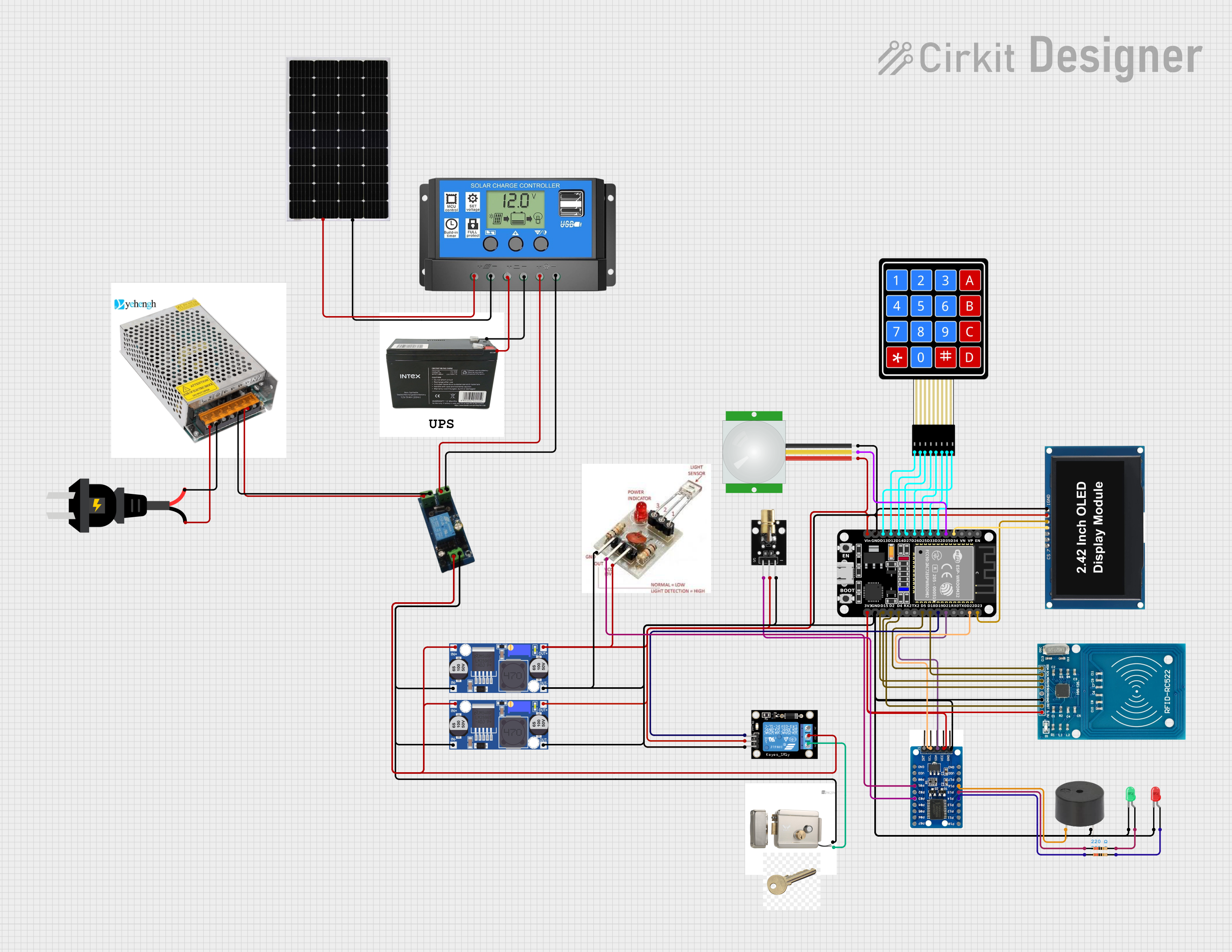 Open Project in Cirkit Designer
Explore Projects Built with esp-12s-3
Open Project in Cirkit DesignerOpen Project in Cirkit DesignerOpen Project in Cirkit DesignerOpen Project in Cirkit DesignerCommon Applications
- Smart home devices (e.g., smart plugs, lights, and thermostats)
- Industrial IoT systems
- Wireless sensor networks
- Remote monitoring and control systems
- Prototyping and development of Wi-Fi-enabled devices
Technical Specifications
Key Technical Details
| Parameter | Value |
|---|---|
| Chipset | ESP8266 |
| Operating Voltage | 3.0V - 3.6V |
| Flash Memory | 4 MB (32 Mbit) |
| Wi-Fi Standards | 802.11 b/g/n |
| Frequency Range | 2.4 GHz |
| GPIO Pins | 11 |
| Communication Protocols | UART, SPI, I2C |
| Power Consumption | 20 mA (idle), 200 mA (peak TX) |
| Dimensions | 24 mm x 16 mm x 3 mm |
| Operating Temperature | -40°C to +125°C |
Pin Configuration and Descriptions
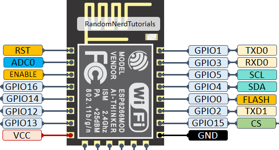
The ESP-12S-3 module has 16 pins. Below is the pinout and description:
| Pin Number | Pin Name | Description |
|---|---|---|
| 1 | GND | Ground connection |
| 2 | TXD | UART Transmit (used for serial communication) |
| 3 | RXD | UART Receive (used for serial communication) |
| 4 | GPIO0 | General-purpose I/O pin; used for boot mode selection during startup |
| 5 | GPIO2 | General-purpose I/O pin |
| 6 | GPIO4 | General-purpose I/O pin |
| 7 | GPIO5 | General-purpose I/O pin |
| 8 | GPIO12 | General-purpose I/O pin |
| 9 | GPIO13 | General-purpose I/O pin |
| 10 | GPIO14 | General-purpose I/O pin |
| 11 | GPIO15 | General-purpose I/O pin; must be pulled low during boot |
| 12 | GPIO16 | General-purpose I/O pin |
| 13 | EN | Chip enable; must be pulled high for normal operation |
| 14 | VCC | Power supply input (3.0V - 3.6V) |
| 15 | RST | Reset pin; active low |
| 16 | ADC | Analog-to-digital converter input (0V - 1V range) |
Usage Instructions
How to Use the ESP-12S-3 in a Circuit
- Power Supply: Connect the VCC pin to a regulated 3.3V power source and GND to ground. Ensure the power supply can handle the peak current of 200 mA.
- Boot Mode:
- Pull GPIO0 low and GPIO15 low during startup to enter programming mode.
- For normal operation, pull GPIO0 high and GPIO15 low.
- Serial Communication: Use the TXD and RXD pins to communicate with a microcontroller or USB-to-serial adapter.
- GPIO Pins: Use the GPIO pins to interface with sensors, actuators, or other peripherals.
- ADC Pin: Connect analog sensors to the ADC pin, ensuring the input voltage does not exceed 1V.
Important Considerations
- Use a level shifter if interfacing with 5V logic devices, as the ESP-12S-3 operates at 3.3V logic levels.
- Add a 10 µF capacitor near the VCC pin to stabilize the power supply.
- Ensure proper grounding to avoid noise and interference in Wi-Fi communication.
- Use an external antenna if the onboard antenna does not provide sufficient range.
Example: Connecting to an Arduino UNO
Below is an example of how to connect the ESP-12S-3 to an Arduino UNO and send data to a Wi-Fi network.
Wiring Diagram
| ESP-12S-3 Pin | Arduino UNO Pin |
|---|---|
| VCC | 3.3V |
| GND | GND |
| TXD | RX (Pin 0) |
| RXD | TX (Pin 1) |
| EN | 3.3V |
| GPIO0 | GND (for programming mode) |
Arduino Code
#include <SoftwareSerial.h>

// Define RX and TX pins for SoftwareSerial
SoftwareSerial espSerial(2, 3); // RX = Pin 2, TX = Pin 3

void setup() {
  Serial.begin(9600); // Start Serial Monitor
  espSerial.begin(9600); // Start communication with ESP-12S-3

  Serial.println("Initializing ESP-12S-3...");
  espSerial.println("AT"); // Send AT command to check communication

  delay(1000); // Wait for response
  while (espSerial.available()) {
    Serial.write(espSerial.read()); // Print ESP response to Serial Monitor
  }
}

void loop() {
  // Example: Send data to ESP-12S-3
  if (Serial.available()) {
    String command = Serial.readString();
    espSerial.println(command); // Send command to ESP-12S-3
  }

  // Print ESP-12S-3 response
  while (espSerial.available()) {
    Serial.write(espSerial.read());
  }
}
Troubleshooting and FAQs
Common Issues
No Response from the Module
- Ensure the EN pin is pulled high.
- Verify the power supply provides a stable 3.3V.
- Check the TXD and RXD connections.
Wi-Fi Connection Fails
- Verify the SSID and password are correct.
- Ensure the router operates on the 2.4 GHz band (not 5 GHz).
- Check for interference from other devices.
Module Overheats
- Ensure the power supply does not exceed 3.6V.
- Avoid prolonged high-current operations.
Tips for Troubleshooting
- Use a multimeter to check voltage levels on the VCC and GND pins.
- Test the module with a simple AT command (
AT) to verify communication. - Use a logic analyzer or oscilloscope to debug serial communication issues.
FAQs
Q: Can the ESP-12S-3 operate on 5V?
A: No, the ESP-12S-3 operates at 3.3V. Use a voltage regulator or level shifter for 5V systems.
Q: How do I update the firmware?
A: Use the UART interface and a compatible flashing tool (e.g., esptool.py) to upload new firmware.
Q: What is the maximum Wi-Fi range?
A: The range depends on environmental factors but typically extends up to 100 meters in open spaces.
This concludes the documentation for the ESP-12S-3 module.