How to Use dm13-5 module: Examples, Pinouts, and Specs

 Design with dm13-5 module in Cirkit Designer
Introduction
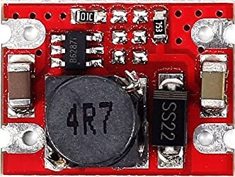
The DM13-5 module is a versatile electronic display panel commonly used in a wide range of electronic devices. It is capable of displaying alphanumeric characters and simple graphics, making it suitable for user interfaces, readouts, and simple visual feedback systems. Its ease of integration into electronic circuits, along with onboard control circuitry, allows for straightforward interfacing with microcontrollers and other components.
Explore Projects Built with dm13-5 module

 Open Project in Cirkit Designer
 Open Project in Cirkit Designer
 Open Project in Cirkit Designer
 Open Project in Cirkit Designer
Explore Projects Built with dm13-5 module

 Open Project in Cirkit Designer
 Open Project in Cirkit Designer
 Open Project in Cirkit Designer
 Open Project in Cirkit Designer
Common Applications and Use Cases
- Digital clocks and timers
- User interface displays for various electronics
- Monitoring displays for sensors and instruments
- Simple graphical representations for games and animations
Technical Specifications
Key Technical Details
- Operating Voltage: Typically 3.3V to 5V
- Current Consumption: Depends on brightness and usage, typically around 20mA
- Display Type: LED/LCD (depending on the specific variant)
- Resolution: Varies by specific model (e.g., 128x64 pixels)
- Interface: I2C/SPI/Parallel (model-specific)
Pin Configuration and Descriptions
| Pin Number | Pin Name | Description |
|---|---|---|
| 1 | VCC | Power supply (3.3V-5V) |
| 2 | GND | Ground connection |
| 3 | SDA | Serial Data (I2C interface) |
| 4 | SCL | Serial Clock (I2C interface) |
| 5 | RES | Reset pin (active low) |
| 6 | DC | Data/Command control pin |
| 7 | CS | Chip Select (active low, SPI interface) |
| 8 | MOSI | Master Out Slave In (SPI interface) |
| 9 | MISO | Master In Slave Out (SPI interface) |
| 10 | SCK | Serial Clock (SPI interface) |
Note: The pin configuration may vary based on the specific variant of the DM13-5 module. Always refer to the manufacturer's datasheet for exact details.
Usage Instructions
How to Use the Component in a Circuit
- Power Connections: Connect the VCC pin to a suitable power supply (3.3V or 5V) and the GND pin to the ground of your circuit.
- Data Interface: Choose the appropriate communication protocol (I2C/SPI) and connect the corresponding pins to your microcontroller.
- Reset and Control: Connect the RES pin to a digital output on your microcontroller for resetting the display. The DC and CS pins are used for command/data selection and chip selection in SPI mode, respectively.
Important Considerations and Best Practices
- Ensure that the power supply voltage matches the module's requirements.
- Use pull-up resistors on the I2C lines if they are not built into the module.
- Avoid long wires for communication lines to minimize signal degradation.
- Implement proper power decoupling with capacitors close to the module's power pins.
Troubleshooting and FAQs
Common Issues Users Might Face
- Display Not Powering On: Check the power supply connections and voltages.
- Garbled or No Output: Verify the communication protocol settings and wiring.
- Dim Display: Adjust the contrast/brightness settings or check for insufficient power supply.
Solutions and Tips for Troubleshooting
- Double-check all connections against the module's datasheet.
- Use example code to test the display independently from your application.
- Ensure that the microcontroller's libraries and firmware are up to date.
FAQs
Q: Can the DM13-5 module be used with an Arduino UNO? A: Yes, the DM13-5 can be interfaced with an Arduino UNO using either I2C or SPI, depending on the module's variant.
Q: What library should I use for the DM13-5 module? A: The library will depend on the specific type of display (e.g., OLED, LCD) and communication protocol. Common libraries include Adafruit_GFX for graphics and Adafruit_SSD1306 for OLED displays.
Q: How do I control the brightness of the display? A: Brightness can typically be controlled through software commands specific to the display controller chip used in the DM13-5 module.
Example Code for Arduino UNO
Below is an example of how to interface the DM13-5 module with an Arduino UNO using the I2C protocol. This example assumes the use of a common OLED display with the SSD1306 controller.
#include <Wire.h>
#include <Adafruit_GFX.h>
#include <Adafruit_SSD1306.h>

// Screen dimensions (change according to your display)
#define SCREEN_WIDTH 128
#define SCREEN_HEIGHT 64

// I2C Address of the display (usually 0x3D or 0x3C)
#define OLED_ADDR   0x3C

// Create an instance of the display
Adafruit_SSD1306 display(SCREEN_WIDTH, SCREEN_HEIGHT, &Wire, -1);

void setup() {
  // Initialize the display
  if(!display.begin(SSD1306_SWITCHCAPVCC, OLED_ADDR)) {
    Serial.println(F("SSD1306 allocation failed"));
    for(;;); // Don't proceed, loop forever
  }

  // Clear the buffer
  display.clearDisplay();

  // Set text size and color
  display.setTextSize(1);
  display.setTextColor(SSD1306_WHITE);

  // Display static text
  display.setCursor(0,0);
  display.println(F("Hello, DM13-5!"));
  display.display();
}

void loop() {
  // Main loop body if needed
}
Note: The above code is for illustrative purposes. Always refer to the specific library documentation and the datasheet of the DM13-5 module for accurate implementation.