How to Use Rele 220 con zocalo: Examples, Pinouts, and Specs
Introduction
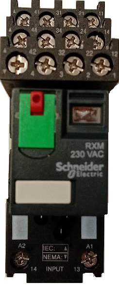
The Rele 220 con Zocalo (Manufacturer: Schneider, Part ID: 0007) is a 220V relay with an integrated socket, designed to control high-voltage circuits by switching them on or off using a low-voltage signal. This component is widely used in automation, industrial control systems, and home automation projects. Its socket simplifies installation and replacement, making it a reliable and user-friendly solution for various applications.
Explore Projects Built with Rele 220 con zocalo

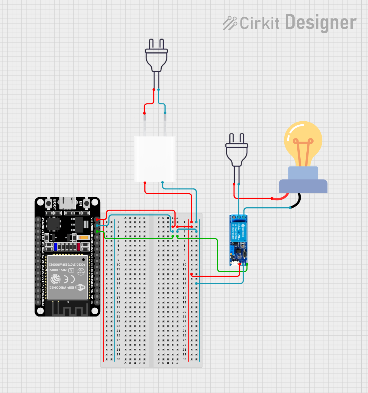
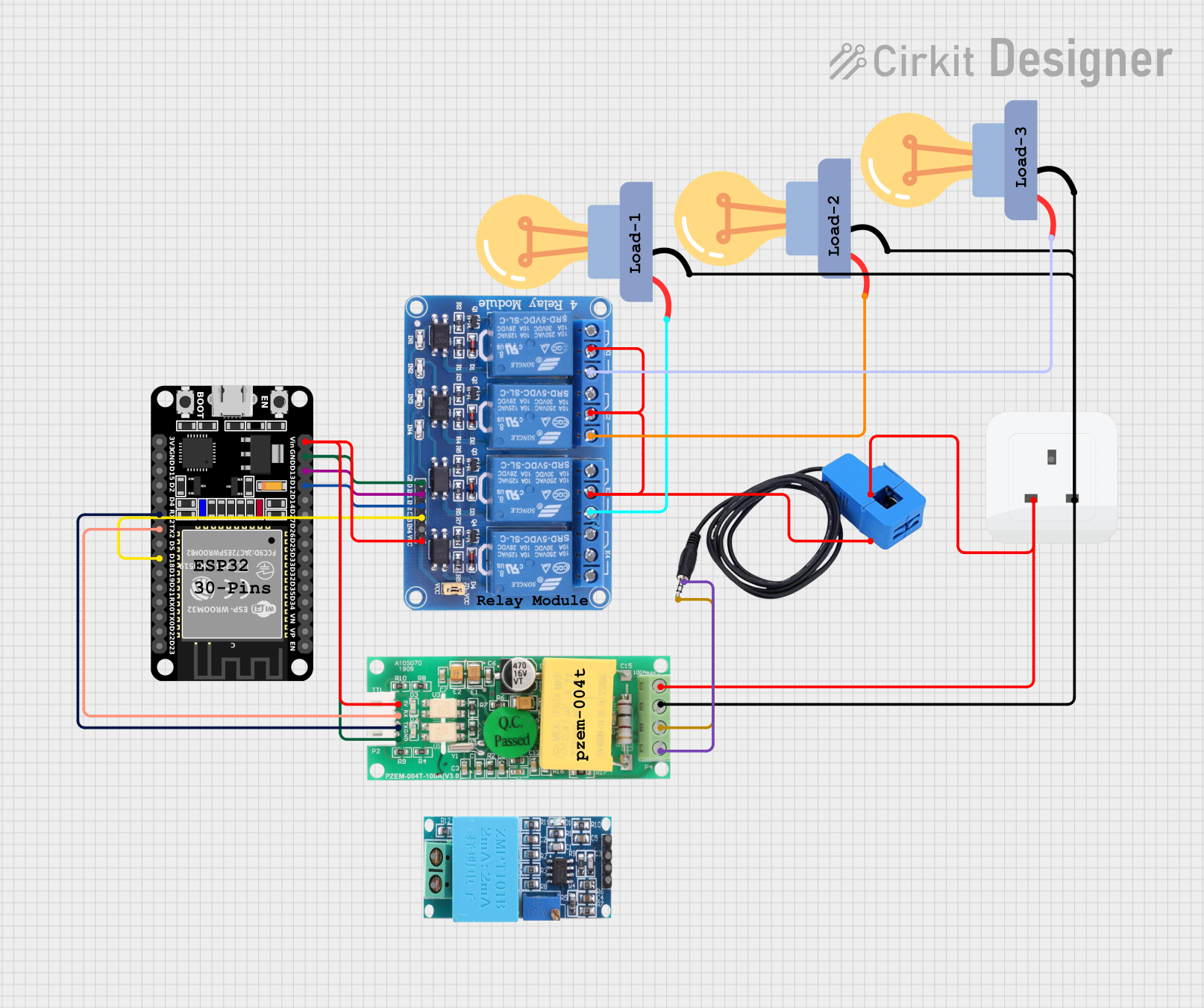

Explore Projects Built with Rele 220 con zocalo
Common Applications
- Industrial machinery control
- Home automation (e.g., controlling lights or appliances)
- Motor control systems
- HVAC systems
- Safety circuits and alarms
Technical Specifications
Key Technical Details
| Parameter | Value |
|---|---|
| Manufacturer | Schneider |
| Part ID | 0007 |
| Operating Voltage (Coil) | 220V AC |
| Switching Voltage | Up to 250V AC / 30V DC |
| Maximum Switching Current | 10A |
| Contact Configuration | SPDT (Single Pole Double Throw) |
| Socket Type | DIN rail mountable |
| Operating Temperature | -40°C to +70°C |
| Insulation Resistance | ≥ 100 MΩ at 500V DC |
| Mechanical Life | 10 million operations |
| Electrical Life | 100,000 operations (at full load) |
Pin Configuration and Descriptions
The relay socket has the following pin layout:
| Pin Number | Description |
|---|---|
| 1 | Coil Terminal 1 (AC Live) |
| 2 | Coil Terminal 2 (AC Neutral) |
| 3 | Common (COM) |
| 4 | Normally Open (NO) |
| 5 | Normally Closed (NC) |
Note: Pins 1 and 2 are used to energize the relay coil, while pins 3, 4, and 5 are used for switching the load.
Usage Instructions
How to Use the Component in a Circuit
Wiring the Coil:
- Connect pin 1 to the live AC line (220V).
- Connect pin 2 to the neutral AC line.
- When the coil is energized, the relay will switch its contacts.
Wiring the Load:
- Connect the load's power source to the Common (COM) terminal (pin 3).
- For a normally open configuration (load is off by default), connect the load to the Normally Open (NO) terminal (pin 4).
- For a normally closed configuration (load is on by default), connect the load to the Normally Closed (NC) terminal (pin 5).
Mounting:
- Secure the relay socket to a DIN rail or a flat surface as required.
- Insert the relay into the socket, ensuring proper alignment.
Testing:
- Apply the control voltage (220V AC) to the coil terminals (pins 1 and 2).
- Verify that the relay switches the load correctly between the NO and NC terminals.
Important Considerations and Best Practices
- Ensure the relay's voltage and current ratings match the requirements of your circuit.
- Use proper insulation and wire gauges to handle high-voltage connections safely.
- Avoid exceeding the relay's maximum switching current to prevent damage.
- For inductive loads (e.g., motors), use a snubber circuit or flyback diode to suppress voltage spikes.
- Regularly inspect the relay for wear and tear, especially in high-duty-cycle applications.
Example: Connecting to an Arduino UNO
The Rele 220 con Zocalo can be controlled using an Arduino UNO by adding an intermediate transistor circuit to drive the 220V AC coil. Below is an example circuit and code:
Circuit Description
- Use an NPN transistor (e.g., 2N2222) to switch the relay coil.
- Connect the Arduino's digital output pin to the transistor's base through a 1kΩ resistor.
- Connect the relay coil terminals (pins 1 and 2) to a 220V AC power source.
- Use a flyback diode (e.g., 1N4007) across the relay coil to protect the transistor from voltage spikes.
Arduino Code
// Define the pin connected to the transistor base
const int relayPin = 7;

void setup() {
  // Set the relay pin as an output
  pinMode(relayPin, OUTPUT);
}

void loop() {
  // Turn the relay ON
  digitalWrite(relayPin, HIGH);
  delay(5000); // Keep the relay ON for 5 seconds

  // Turn the relay OFF
  digitalWrite(relayPin, LOW);
  delay(5000); // Keep the relay OFF for 5 seconds
}
Note: Ensure proper isolation between the Arduino and the high-voltage side of the circuit to avoid damage or safety hazards.
Troubleshooting and FAQs
Common Issues and Solutions
| Issue | Possible Cause | Solution |
|---|---|---|
| Relay does not switch | Coil not receiving power | Check the coil connections (pins 1, 2) |
| Load not turning on/off | Incorrect wiring of load terminals | Verify connections to COM, NO, and NC |
| Relay buzzing or chattering | Insufficient coil voltage | Ensure 220V AC is supplied to the coil |
| Overheating of relay | Exceeding current rating | Reduce load current or use a higher-rated relay |
| Arduino not controlling the relay | Missing transistor or incorrect wiring | Add a transistor circuit to drive the relay |
FAQs
Can this relay be used with DC loads?
- Yes, the relay can switch DC loads up to 30V and 10A. Ensure proper wiring and ratings.
Is the relay socket replaceable?
- Yes, the socket is designed for easy replacement and maintenance.
Can I use this relay for motor control?
- Yes, but for inductive loads like motors, use a snubber circuit or flyback diode to protect the relay.
What safety precautions should I take?
- Always disconnect power before wiring or replacing the relay. Use proper insulation and avoid touching live wires.
By following this documentation, you can effectively use the Rele 220 con Zocalo in your projects while ensuring safety and reliability.