
How to Use Modulo 817: Examples, Pinouts, and Specs
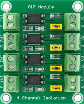
 Design with Modulo 817 in Cirkit Designer
Introduction
The Modulo 817 is a versatile integrated circuit (IC) designed for analog signal processing. It is commonly used in applications requiring precision voltage regulation, signal conditioning, and noise filtering. Its robust design and high accuracy make it ideal for use in audio systems, instrumentation, and industrial control circuits. The Modulo 817 is particularly valued for its ability to maintain stable performance in environments with fluctuating power supplies or high levels of electrical noise.
Explore Projects Built with Modulo 817
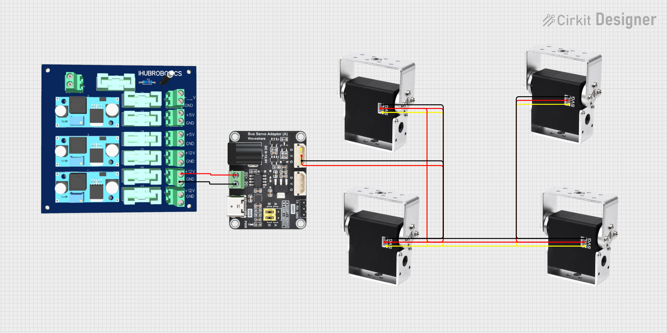 Open Project in Cirkit Designer
 Open Project in Cirkit Designer
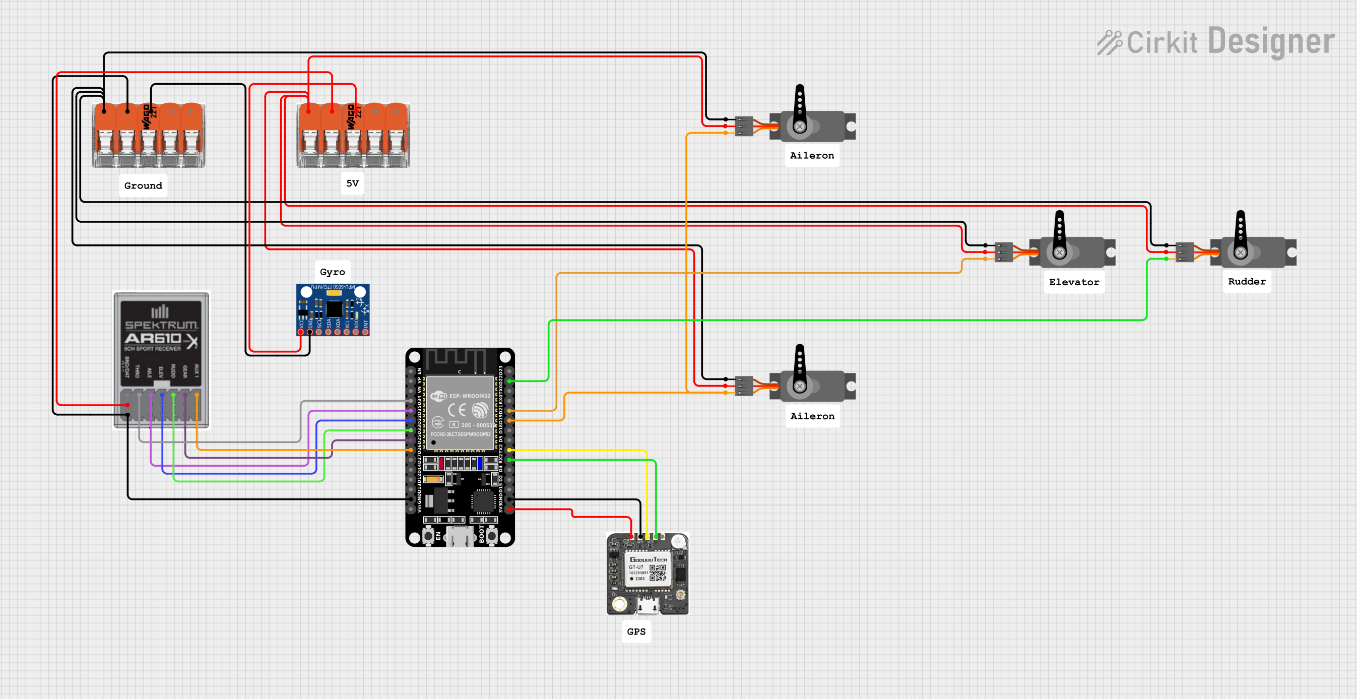 Open Project in Cirkit Designer
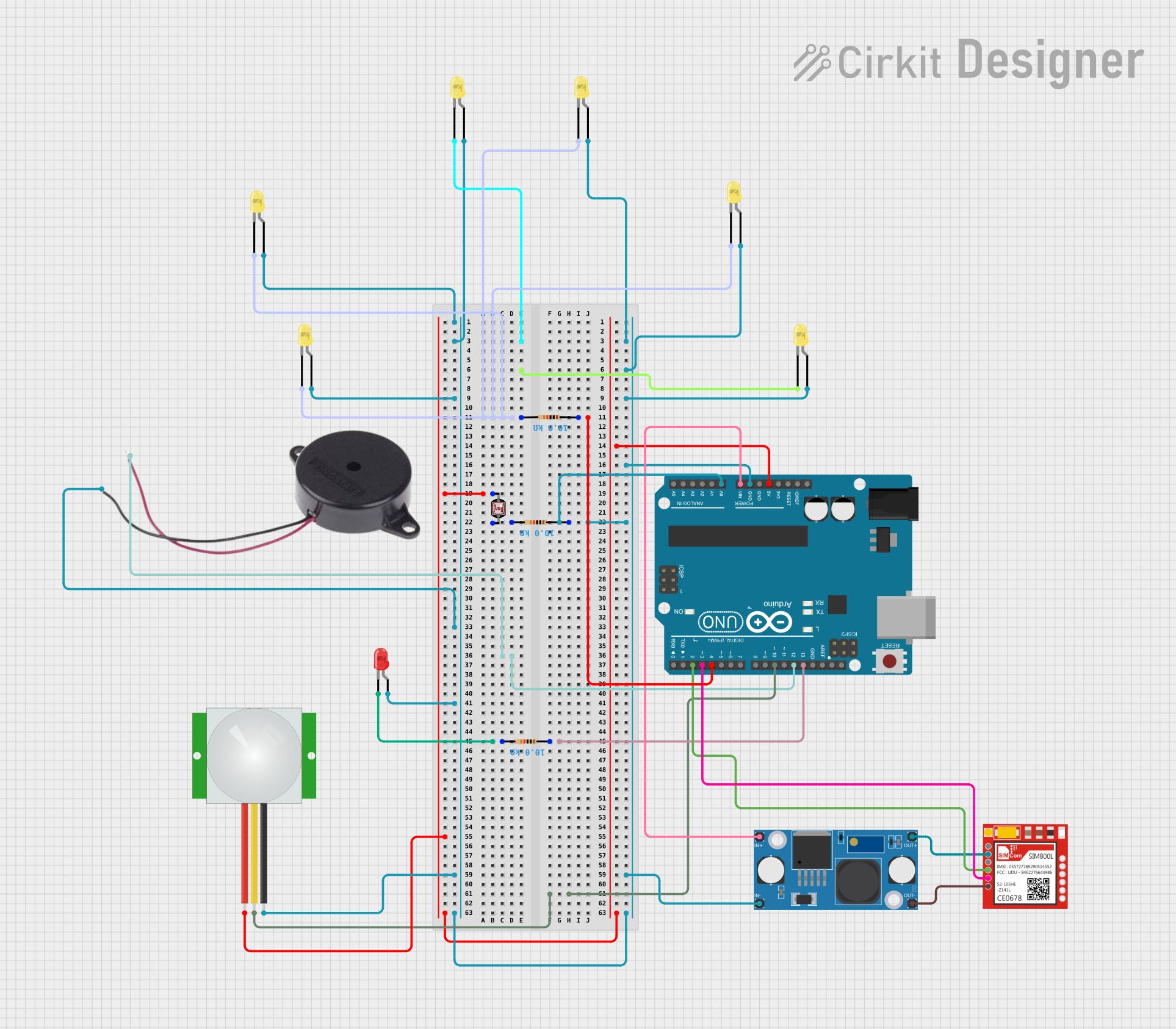 Open Project in Cirkit Designer
Explore Projects Built with Modulo 817
Open Project in Cirkit DesignerOpen Project in Cirkit DesignerOpen Project in Cirkit DesignerOpen Project in Cirkit DesignerCommon Applications:
- Precision voltage regulation in power supply circuits
- Signal conditioning in audio and instrumentation systems
- Noise filtering in industrial control systems
- Analog-to-digital conversion support circuits
Technical Specifications
Below are the key technical details of the Modulo 817:
| Parameter | Value |
|---|---|
| Supply Voltage (Vcc) | 3.3V to 15V |
| Operating Current | 2 mA (typical) |
| Output Voltage Range | 0V to Vcc |
| Input Impedance | 1 MΩ |
| Output Impedance | 50 Ω |
| Temperature Range | -40°C to +85°C |
| Package Type | DIP-8, SOIC-8 |
Pin Configuration and Descriptions
The Modulo 817 is typically available in an 8-pin package. Below is the pinout and description:
| Pin Number | Pin Name | Description |
|---|---|---|
| 1 | Vcc | Positive power supply input |
| 2 | IN+ | Non-inverting input for the analog signal |
| 3 | IN- | Inverting input for the analog signal |
| 4 | GND | Ground connection |
| 5 | OUT | Analog output signal |
| 6 | NC | No connection (leave unconnected) |
| 7 | REF | Reference voltage input for precision regulation |
| 8 | ENABLE | Enable/disable control for the IC |
Usage Instructions
How to Use the Modulo 817 in a Circuit
- Power Supply: Connect the Vcc pin to a stable power source within the range of 3.3V to 15V. Connect the GND pin to the circuit ground.
- Signal Input: Feed the analog signal to be processed into the IN+ and IN- pins. The IN+ pin is for the non-inverting input, while the IN- pin is for the inverting input.
- Output: The processed signal will be available at the OUT pin. Connect this pin to the next stage of your circuit (e.g., an ADC or amplifier).
- Reference Voltage: If precision voltage regulation is required, provide a stable reference voltage to the REF pin. Otherwise, this pin can be left unconnected.
- Enable Control: Use the ENABLE pin to turn the IC on or off. Pull this pin high to enable the IC or low to disable it.
Important Considerations and Best Practices
- Decoupling Capacitors: Place a 0.1 µF ceramic capacitor close to the Vcc pin to filter out high-frequency noise.
- Input Signal Range: Ensure the input signal voltage does not exceed the supply voltage to avoid damage to the IC.
- Thermal Management: Operate the IC within the specified temperature range to prevent thermal damage.
- Unused Pins: Leave the NC pin unconnected and avoid grounding or connecting it to any signal.
Example: Using Modulo 817 with Arduino UNO
The Modulo 817 can be used with an Arduino UNO for signal conditioning. Below is an example of how to read an analog signal processed by the Modulo 817:
// Example: Reading an analog signal processed by Modulo 817
const int analogPin = A0; // Connect OUT pin of Modulo 817 to Arduino A0
int analogValue = 0;      // Variable to store the analog value

void setup() {
  Serial.begin(9600); // Initialize serial communication at 9600 baud
}

void loop() {
  analogValue = analogRead(analogPin); // Read the analog value from Modulo 817
  Serial.print("Analog Value: ");
  Serial.println(analogValue); // Print the value to the Serial Monitor
  delay(500); // Wait for 500ms before the next reading
}
Troubleshooting and FAQs
Common Issues and Solutions
No Output Signal:
- Cause: The ENABLE pin is not connected or is pulled low.
- Solution: Ensure the ENABLE pin is pulled high to activate the IC.
Distorted Output Signal:
- Cause: Input signal exceeds the supply voltage range.
- Solution: Verify that the input signal voltage is within the specified range.
Unstable Output:
- Cause: Insufficient decoupling on the power supply.
- Solution: Add a 0.1 µF ceramic capacitor close to the Vcc pin.
Overheating:
- Cause: Operating the IC outside the recommended temperature range.
- Solution: Ensure proper thermal management and operate within the specified range.
FAQs
Q1: Can the Modulo 817 handle digital signals?
A1: No, the Modulo 817 is designed for analog signal processing and is not suitable for digital signals.
Q2: What happens if the REF pin is left unconnected?
A2: If the REF pin is left unconnected, the IC will operate with its internal reference voltage, which may not provide the same level of precision as an external reference.
Q3: Can I use the Modulo 817 with a 5V power supply?
A3: Yes, the Modulo 817 supports a supply voltage range of 3.3V to 15V, so a 5V power supply is compatible.
Q4: Is the Modulo 817 suitable for battery-powered applications?
A4: Yes, its low operating current (2 mA typical) makes it suitable for battery-powered applications.