How to Use Solar Panel Regulator 5A MPPT Controller Battery Charging 9V/12V/24V/Auto Switch: Examples, Pinouts, and Specs
Introduction
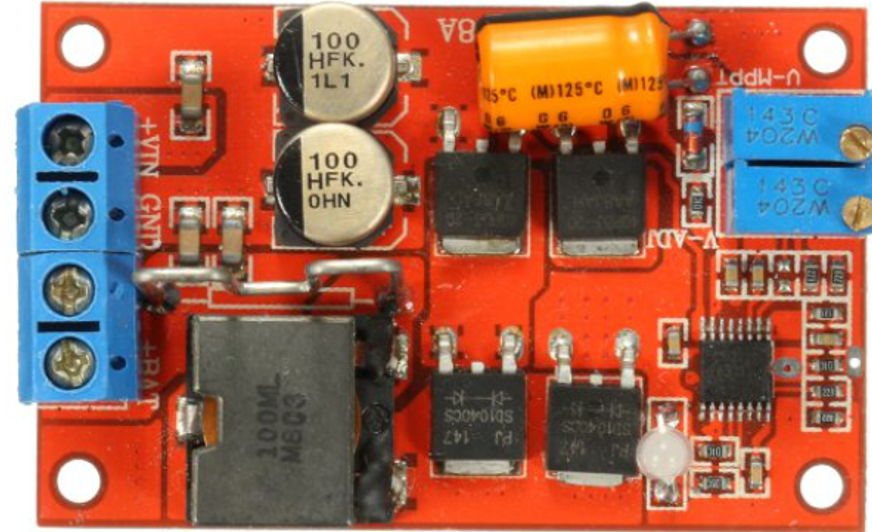
The Solar Panel Regulator 5A MPPT Controller is an advanced charging device designed to optimize the charging of batteries from solar panels. It employs Maximum Power Point Tracking (MPPT) technology to ensure that solar panels operate at their optimum power output, which can significantly increase the efficiency of the solar power system. This regulator is versatile, supporting multiple battery voltages including 9V, 12V, 24V, and an Auto Switch mode that automatically adjusts to the connected battery's voltage. It is commonly used in off-grid solar applications such as remote sensors, RVs, boats, and small off-grid homes.
Explore Projects Built with Solar Panel Regulator 5A MPPT Controller Battery Charging 9V/12V/24V/Auto Switch
Explore Projects Built with Solar Panel Regulator 5A MPPT Controller Battery Charging 9V/12V/24V/Auto Switch
Technical Specifications
Key Technical Details
- Rated Charge Current: 5A
- Maximum PV Input Voltage: 100V
- Battery Voltage Options: 9V, 12V, 24V, Auto Switch
- Maximum PV Input Power:
- 60W (for 9V battery)
- 120W (for 12V battery)
- 240W (for 24V battery)
- Self-Consumption: ≤10mA
- Charge Mode: MPPT
- Temperature Compensation: -3mV/°C/2V (adjustable)
- Operating Temperature: -35°C to +60°C
Pin Configuration and Descriptions
| Pin Number | Function | Description |
|---|---|---|
| 1 | PV+ | Positive terminal for solar panel input |
| 2 | PV- | Negative terminal for solar panel input |
| 3 | BAT+ | Positive terminal for battery connection |
| 4 | BAT- | Negative terminal for battery connection |
| 5 | Load+ | Positive terminal for load output |
| 6 | Load- | Negative terminal for load output |
| 7 | Temp Sensor (opt) | Connection for optional external temperature sensor |
| 8 | Remote (opt) | Connection for optional remote monitoring/control |
Usage Instructions
How to Use the Component in a Circuit
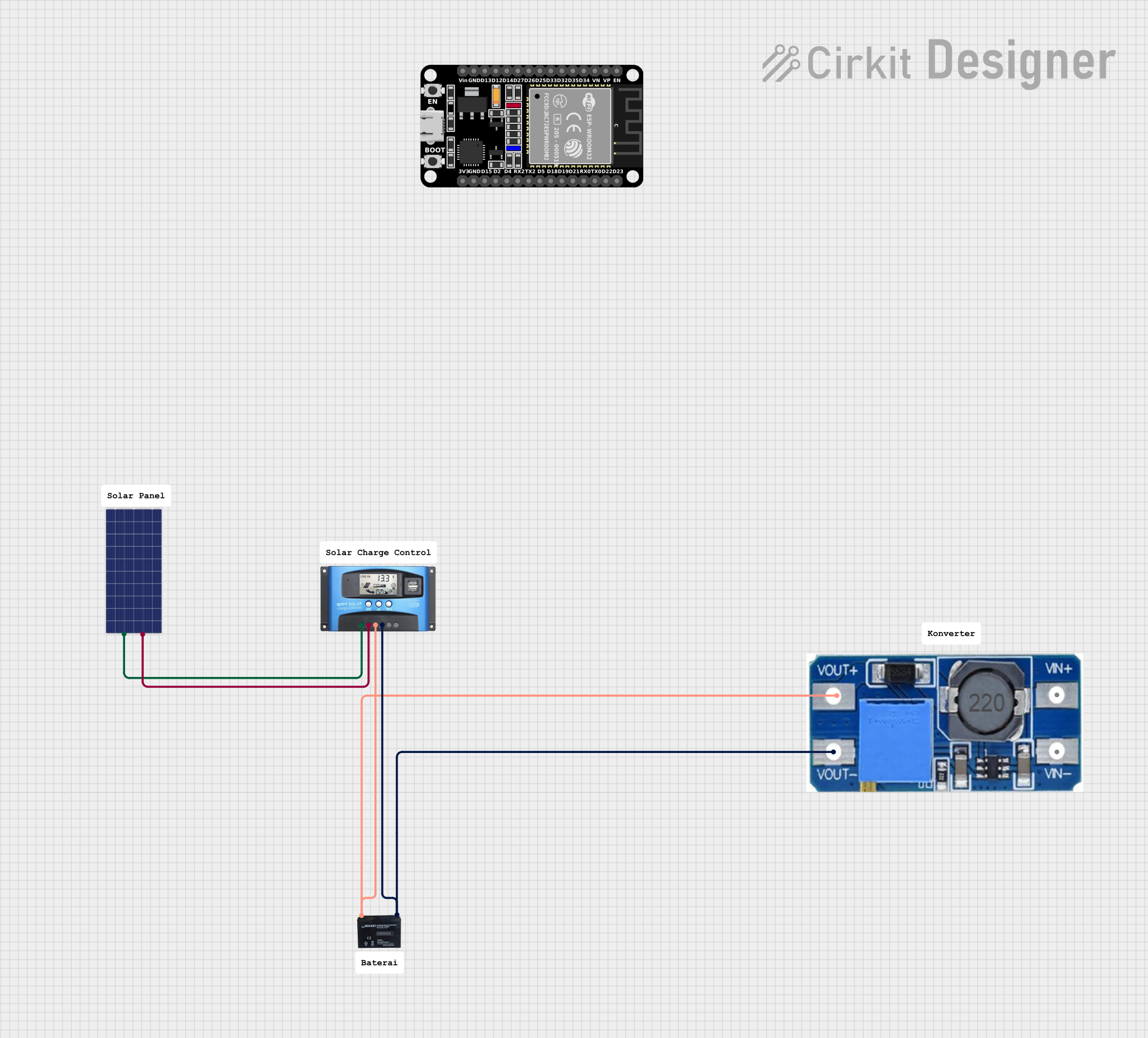
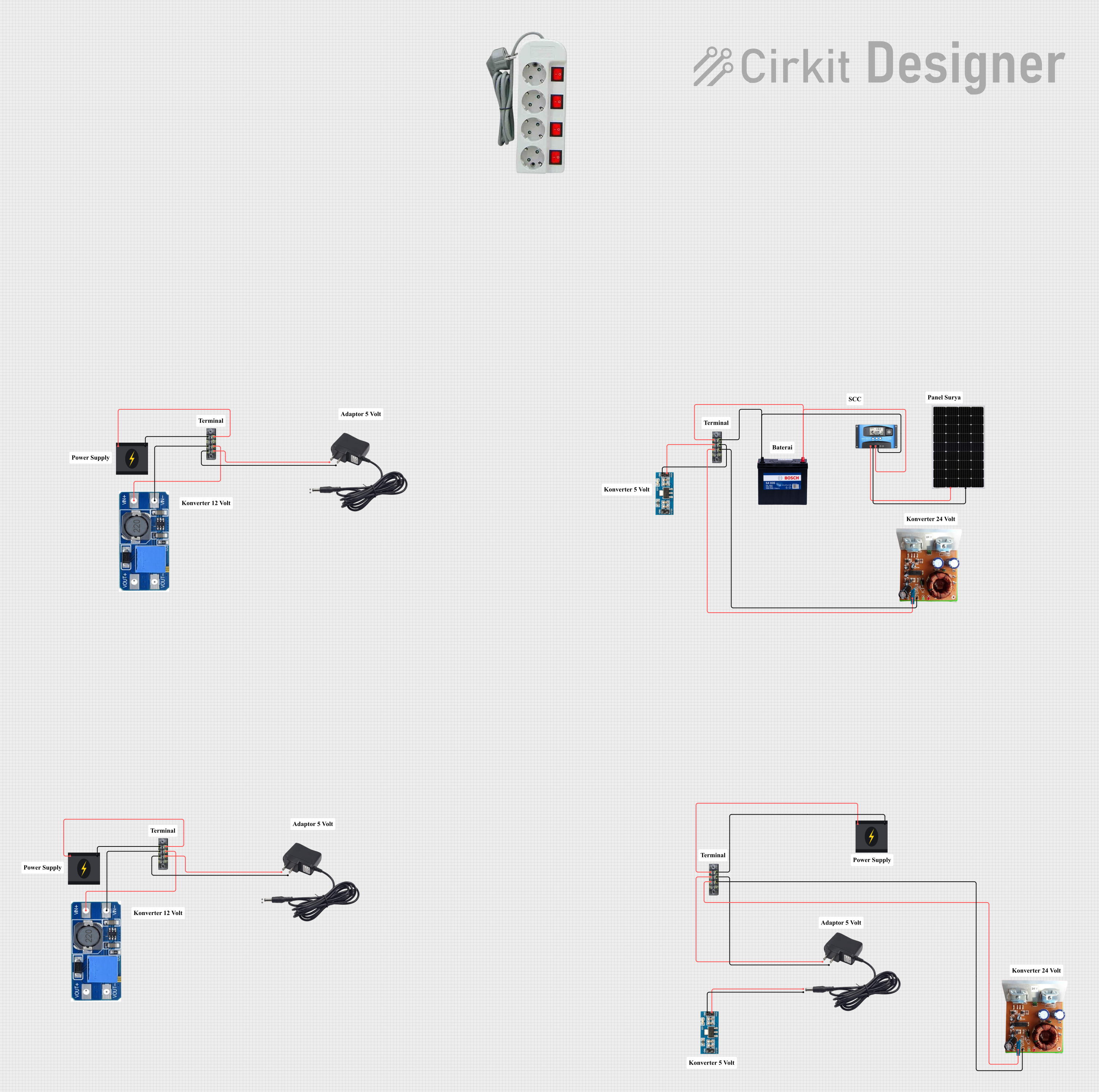
Connecting the Battery:
- Ensure the battery voltage matches the regulator setting or is set to Auto Switch.
- Connect the battery's positive terminal to the BAT+ pin and the negative terminal to the BAT- pin.
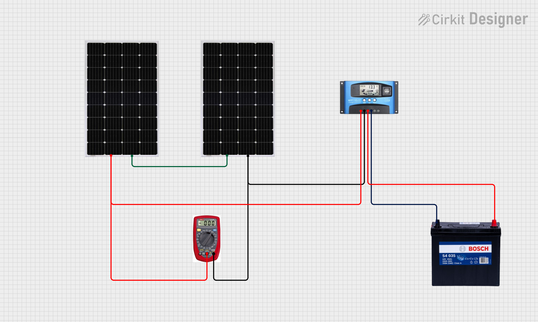
Connecting the Solar Panel:
- Verify that the solar panel's voltage does not exceed the maximum PV input voltage.
- Connect the solar panel's positive terminal to the PV+ pin and the negative terminal to the PV- pin.
Connecting the Load:
- Connect the load's positive terminal to the Load+ pin and the negative terminal to the Load- pin.
Setting Up the Controller:
- If available, connect the temperature sensor to the Temp Sensor pin for more accurate charging.
- For remote monitoring or control, connect the appropriate device to the Remote pin.
Important Considerations and Best Practices
- Always connect the battery first to power up the regulator before connecting the solar panel.
- Ensure that all connections are secure and that the correct polarity is maintained to prevent damage.
- Do not exceed the rated charge current and PV input voltage to avoid overloading the controller.
- Use appropriate cable sizes to minimize voltage drop, especially for longer cable runs.
- Protect the controller from extreme weather conditions by placing it in a weatherproof enclosure if used outdoors.
- Regularly check the connections and clean the solar panels to maintain optimal performance.
Troubleshooting and FAQs
Common Issues and Solutions
The controller is not charging the battery:
- Check all connections for proper polarity and secure fit.
- Verify that the solar panel is receiving sufficient sunlight and is not shaded.
- Ensure the solar panel voltage falls within the acceptable range.
The load is not powered:
- Confirm that the battery has sufficient charge to power the load.
- Check the load connections and ensure the controller's load output is not in a protection mode.
The controller displays error codes or LED indicators:
- Refer to the manufacturer's manual for specific error codes and troubleshooting steps.
FAQs
Q: Can I use this controller with any type of battery?
- A: This controller is compatible with most battery types, but always check the manufacturer's recommendations.
Q: What is the maximum wire size that can be used for connections?
- A: The maximum wire size is typically determined by the terminal block on the controller. Refer to the manufacturer's specifications for details.
Q: How do I know if the MPPT function is working correctly?
- A: The MPPT function is working if the controller is adjusting the PV input to maximize the power output, which can be observed through the increase in charging current during peak sunlight conditions.
For any further assistance, consult the manufacturer's technical support or refer to the detailed user manual that comes with the product.
Example Arduino UNO Connection Code
// Note: This is a hypothetical example as the MPPT controller typically does not require code to operate.
// However, if you were to interface with it for monitoring purposes, the code might look something like this:

#include <SoftwareSerial.h>

SoftwareSerial mpptSerial(10, 11); // RX, TX

void setup() {
  mpptSerial.begin(9600);
  Serial.begin(9600);
}

void loop() {
  if (mpptSerial.available()) {
    String mpptData = mpptSerial.readStringUntil('\n');
    Serial.println("MPPT Data: " + mpptData);
  }
  // Add code here to interpret the data and perform actions as needed.
  // This could include monitoring battery voltage, current, and power output.
}
Please note that the above code is for illustrative purposes only and may not directly apply to the Solar Panel Regulator 5A MPPT Controller. Always refer to the specific communication protocol and connection interface provided by the manufacturer for accurate integration with microcontrollers or other devices.