Cirkit Designer Logo
Cirkit Designer
Your all-in-one circuit design IDE
Home / 
Component Documentation

How to Use Bridge rectifier: Examples, Pinouts, and Specs

Image of Bridge rectifier
Cirkit Designer LogoDesign with Bridge rectifier in Cirkit Designer

Introduction

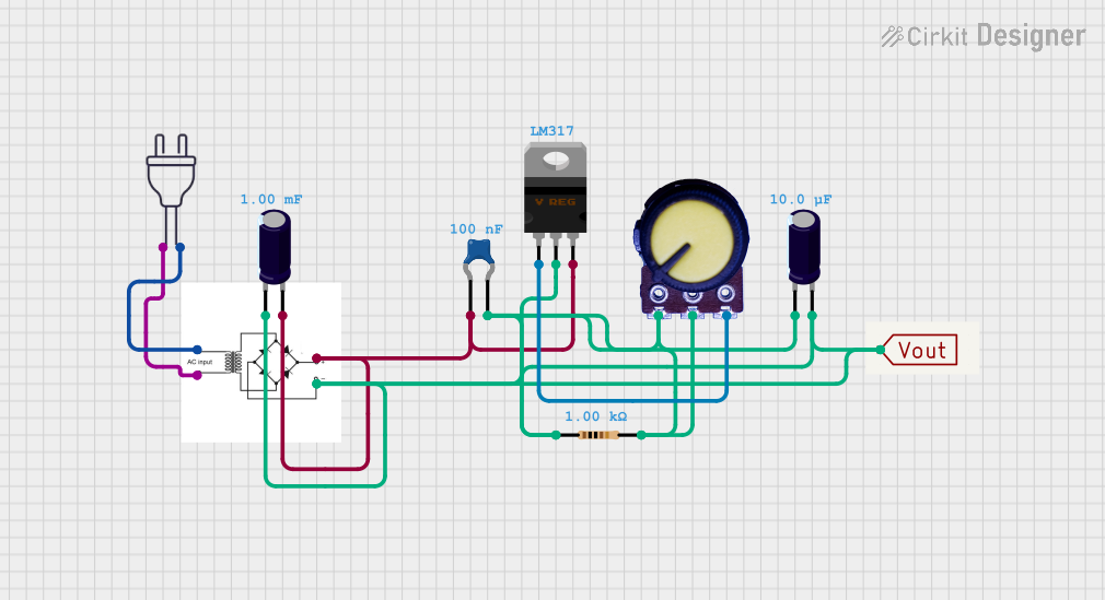
A bridge rectifier is an electronic component that converts alternating current (AC) to direct current (DC). It is a critical component in power supply design and is widely used in various electronic devices where a stable DC voltage is required. The bridge rectifier is preferred over a single diode rectifier due to its ability to provide full-wave rectification, which allows for better efficiency and smoother DC output.

Explore Projects Built with Bridge rectifier

Use Cirkit Designer to design, explore, and prototype these projects online. Some projects support real-time simulation. Click "Open Project" to start designing instantly!
DC Motor-Controlled LED Array with Bridge Rectifier
Image of Generation of electricity by speed breaker: A project utilizing Bridge rectifier in a practical application
This circuit consists of a DC gear motor connected to a bridge rectifier, which suggests that the rectifier is used to convert an AC input to a DC output for the motor. Additionally, there are multiple red LEDs connected in parallel across the rectified output, likely serving as indicators for the presence of DC power after rectification.
Cirkit Designer LogoOpen Project in Cirkit Designer
Battery-Powered Motor Control with Voltage Monitoring and LED Indicator
Image of ckt: A project utilizing Bridge rectifier in a practical application
This circuit converts AC power to DC using a bridge rectifier to drive a 12V geared motor. It also includes a TP4056 module for charging a 3.7V battery, monitored by a mini digital volt/ammeter, and an LED indicator for power status.
Cirkit Designer LogoOpen Project in Cirkit Designer
Solar-Powered 3.7V Battery Charging System with BMS and Power Regulation
Image of Transmission part: A project utilizing Bridge rectifier in a practical application
This circuit appears to be a solar-powered battery charging system with voltage regulation and rectification. The solar panel's output is rectified by a bridge rectifier and then used to charge a series of 3.7V batteries managed by a 3s 20A BMS (Battery Management System). Additional components like MOSFETs, capacitors, and diodes are used for controlling the charging process and smoothing the output, while a transformer and power input suggest an alternative charging method or a power supply functionality.
Cirkit Designer LogoOpen Project in Cirkit Designer
LM317 Voltage Regulator Circuit with Bridge Rectifier for Stable DC Output
Image of voltage regualator using LM317 IC: A project utilizing Bridge rectifier in a practical application
This circuit converts 220V AC to a regulated DC voltage using a bridge rectifier, smoothing capacitors, and an LM317 voltage regulator. The output voltage can be adjusted using a potentiometer connected to the LM317's adjustment pin.
Cirkit Designer LogoOpen Project in Cirkit Designer

Explore Projects Built with Bridge rectifier

Use Cirkit Designer to design, explore, and prototype these projects online. Some projects support real-time simulation. Click "Open Project" to start designing instantly!
Image of Generation of electricity by speed breaker: A project utilizing Bridge rectifier in a practical application
DC Motor-Controlled LED Array with Bridge Rectifier
This circuit consists of a DC gear motor connected to a bridge rectifier, which suggests that the rectifier is used to convert an AC input to a DC output for the motor. Additionally, there are multiple red LEDs connected in parallel across the rectified output, likely serving as indicators for the presence of DC power after rectification.
Cirkit Designer LogoOpen Project in Cirkit Designer
Image of ckt: A project utilizing Bridge rectifier in a practical application
Battery-Powered Motor Control with Voltage Monitoring and LED Indicator
This circuit converts AC power to DC using a bridge rectifier to drive a 12V geared motor. It also includes a TP4056 module for charging a 3.7V battery, monitored by a mini digital volt/ammeter, and an LED indicator for power status.
Cirkit Designer LogoOpen Project in Cirkit Designer
Image of Transmission part: A project utilizing Bridge rectifier in a practical application
Solar-Powered 3.7V Battery Charging System with BMS and Power Regulation
This circuit appears to be a solar-powered battery charging system with voltage regulation and rectification. The solar panel's output is rectified by a bridge rectifier and then used to charge a series of 3.7V batteries managed by a 3s 20A BMS (Battery Management System). Additional components like MOSFETs, capacitors, and diodes are used for controlling the charging process and smoothing the output, while a transformer and power input suggest an alternative charging method or a power supply functionality.
Cirkit Designer LogoOpen Project in Cirkit Designer
Image of voltage regualator using LM317 IC: A project utilizing Bridge rectifier in a practical application
LM317 Voltage Regulator Circuit with Bridge Rectifier for Stable DC Output
This circuit converts 220V AC to a regulated DC voltage using a bridge rectifier, smoothing capacitors, and an LM317 voltage regulator. The output voltage can be adjusted using a potentiometer connected to the LM317's adjustment pin.
Cirkit Designer LogoOpen Project in Cirkit Designer

Common Applications and Use Cases

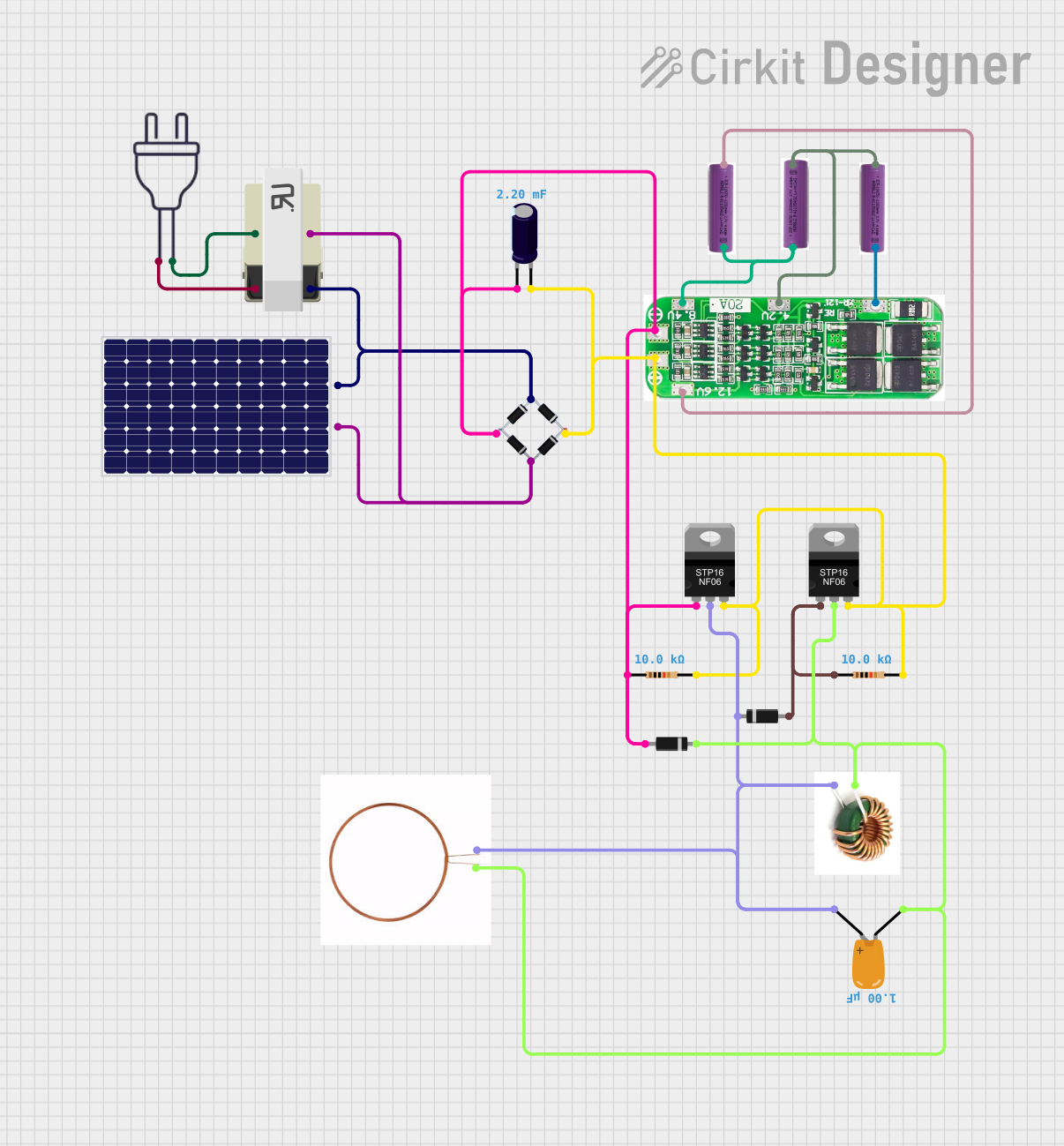
  • Power supplies for electronic devices
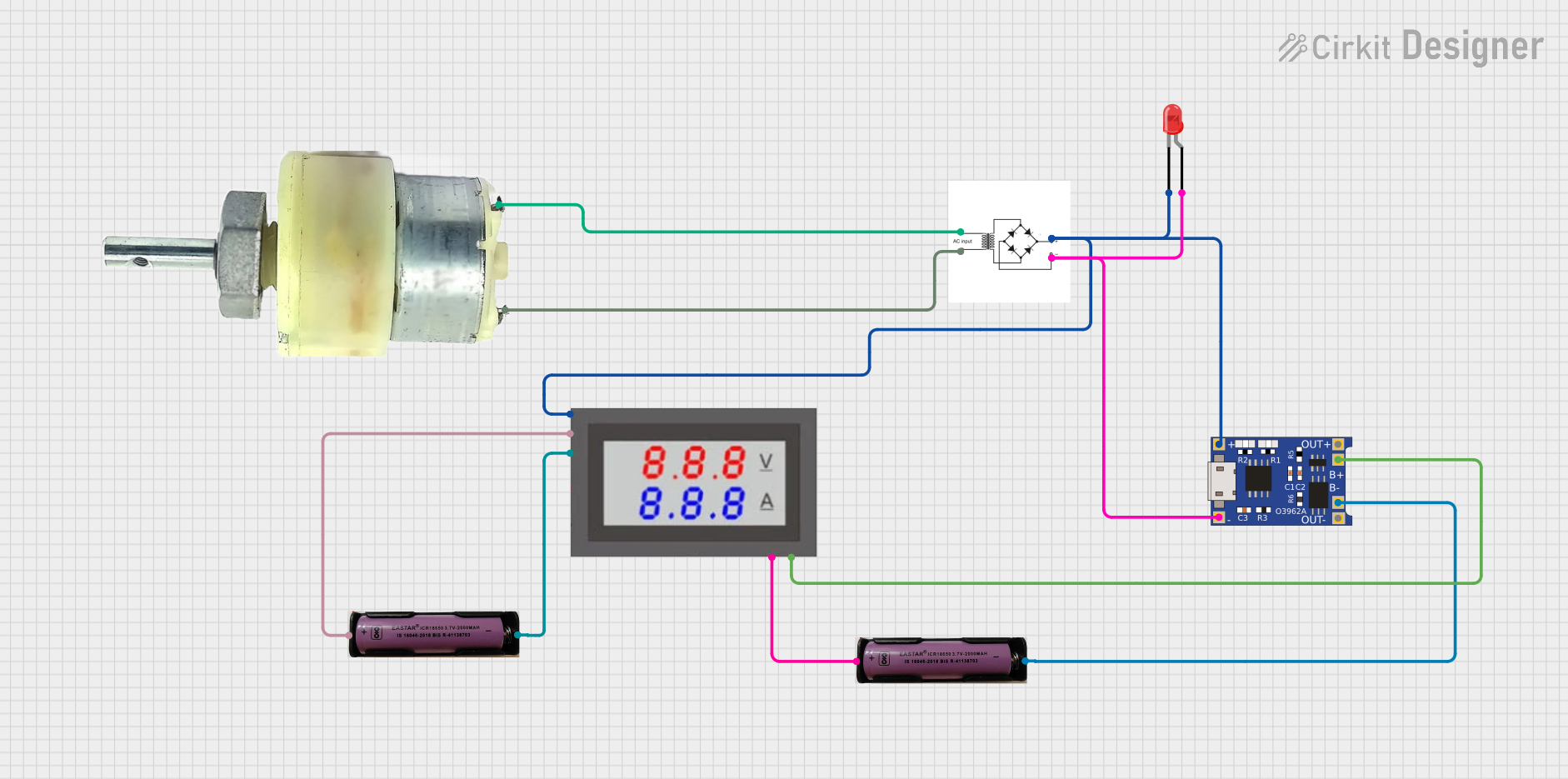
  • Battery charging circuits
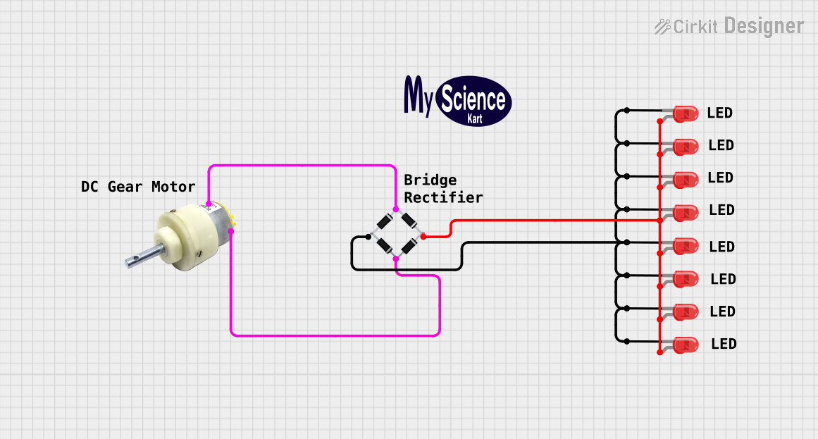
  • DC motor drives
  • Rectification in power inverters

Technical Specifications

Key Technical Details

  • Maximum repetitive peak reverse voltage (VRRM): The maximum voltage the diode can withstand in the reverse direction.
  • Average forward current (IF(AV)): The maximum average current the diodes can conduct.
  • Surge current (IFSM): The maximum peak, one-cycle non-repetitive surge current.
  • Forward voltage drop (VF): The voltage drop across the diode when it is conducting.
  • Operating junction temperature range (TJ): The range of temperatures over which the diode can operate without damage.

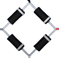
Pin Configuration and Descriptions

Pin Number Description
1 AC Input (Phase)
2 AC Input (Neutral)
3 Positive DC Output
4 Negative DC Output

Usage Instructions

How to Use the Component in a Circuit

  1. Connect the AC input terminals (pins 1 and 2) to the AC voltage source.
  2. Connect the positive DC output terminal (pin 3) to the positive side of the load or circuit.
  3. Connect the negative DC output terminal (pin 4) to the negative side of the load or circuit.
  4. Optionally, add a filter capacitor across the DC output to smooth the DC voltage.

Important Considerations and Best Practices

  • Ensure the bridge rectifier's voltage and current ratings exceed the AC source's maximum output.
  • Use a heatsink if the rectifier is expected to handle high power levels to prevent overheating.
  • Place a fuse before the AC input for safety and overcurrent protection.
  • The filter capacitor should be rated for a voltage higher than the peak output voltage of the rectifier.

Troubleshooting and FAQs

Common Issues Users Might Face

  • Excessive voltage drop: This could be due to a high load current or a bridge rectifier with a high forward voltage drop.
  • Overheating: Caused by high current flow or insufficient cooling.
  • Output voltage fluctuations: This may occur if the filter capacitor is failing or is of inadequate value.

Solutions and Tips for Troubleshooting

  • Verify that the bridge rectifier's ratings are suitable for the application.
  • Check for proper heatsink installation and thermal management.
  • Replace the filter capacitor with one of appropriate value and voltage rating.

FAQs

Q: Can I use a bridge rectifier to convert 220V AC to 12V DC? A: Yes, but you will also need a step-down transformer before the rectifier and a voltage regulator after it to achieve a stable 12V DC output.

Q: How do I choose the right filter capacitor? A: The capacitor value depends on the load current and the desired ripple voltage. A common rule of thumb is 1000 µF per ampere of load current.

Q: What happens if I reverse the AC input connections? A: Reversing the AC input connections will not damage the bridge rectifier, as it is non-polarized at the AC input. The DC output polarity will remain the same.

Example Connection with Arduino UNO

// No specific code is required for a bridge rectifier when used with an Arduino UNO.
// The bridge rectifier is a passive component used in the power supply section
// to provide the necessary DC voltage to the Arduino.

// However, ensure that the output voltage from the bridge rectifier is regulated
// and does not exceed the voltage limits of the Arduino board (typically 5V or 3.3V).

Note: The bridge rectifier itself does not require any control or interfacing code, as it is a passive component used for power conversion. The example above is a placeholder to indicate that the bridge rectifier would be part of the power supply circuit for the Arduino UNO, not directly interfaced with the microcontroller.