How to Use Stemma QT 5-port Passive Hub: Examples, Pinouts, and Specs
Introduction
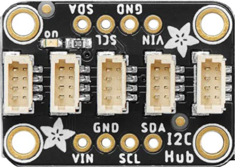
The Stemma QT 5-port Passive Hub (Adafruit Part ID: 5625) is a compact and versatile hub designed to simplify the connection of multiple Stemma QT sensors to a single microcontroller. This hub enables seamless integration and communication between I²C devices without requiring soldering, making it an excellent choice for rapid prototyping and development.
With five Stemma QT connectors, this passive hub allows users to daisy-chain multiple sensors or modules, reducing wiring complexity and ensuring a clean, organized setup. It is particularly useful in projects involving multiple I²C peripherals, such as environmental sensors, displays, or input devices.
Explore Projects Built with Stemma QT 5-port Passive Hub
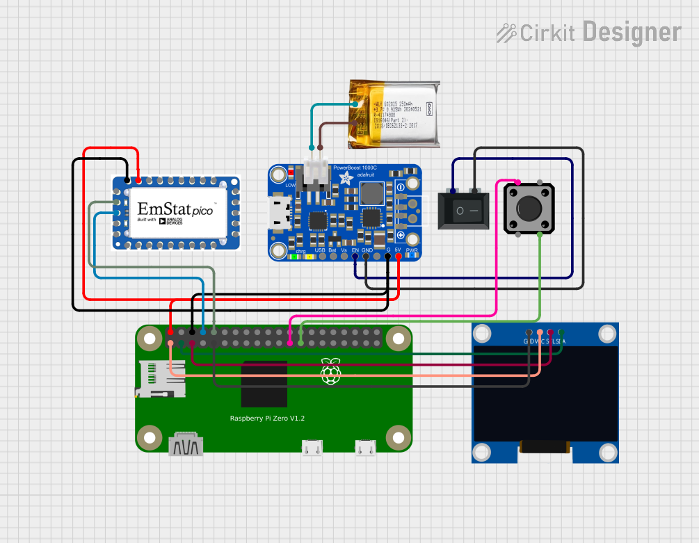


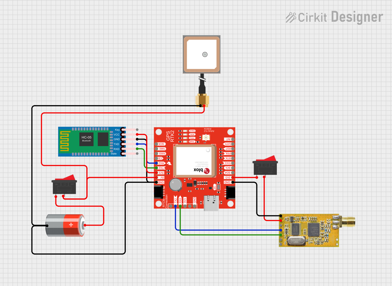
Explore Projects Built with Stemma QT 5-port Passive Hub
Common Applications
- Prototyping with multiple I²C sensors or modules
- Educational projects and STEM learning
- IoT (Internet of Things) devices
- Robotics and automation systems
- Environmental monitoring systems
Technical Specifications
The Stemma QT 5-port Passive Hub is designed to work seamlessly with Adafruit's Stemma QT ecosystem and other compatible I²C devices. Below are the key technical details:
Key Specifications
| Parameter | Value |
|---|---|
| Manufacturer | Adafruit |
| Part ID | 5625 |
| Number of Ports | 5 Stemma QT connectors |
| Communication Protocol | I²C |
| Voltage Range | 3.3V to 5V |
| Dimensions | 25mm x 25mm x 4mm |
| Mounting | 4 mounting holes for secure placement |
| Compatibility | Stemma QT and Qwiic I²C devices |
Pin Configuration and Descriptions
The Stemma QT 5-port Passive Hub does not have traditional pins but instead features five Stemma QT connectors. Each connector has the following pinout:
| Pin Name | Description |
|---|---|
| GND | Ground connection |
| VIN | Power input (3.3V or 5V) |
| SDA | I²C data line |
| SCL | I²C clock line |
All five connectors are internally connected in parallel, allowing devices to share the same I²C bus.
Usage Instructions
How to Use the Stemma QT 5-port Passive Hub
Connect the Hub to a Microcontroller:
- Use a Stemma QT cable to connect one of the hub's ports to the Stemma QT connector on your microcontroller or development board (e.g., Arduino UNO with a Stemma QT adapter).
Connect Sensors or Modules:
- Plug compatible Stemma QT or Qwiic devices into the remaining ports on the hub. Ensure that each device has a unique I²C address to avoid conflicts.
Power the Hub:
- The hub is powered through the VIN and GND lines of the Stemma QT connectors. Ensure your microcontroller provides the appropriate voltage (3.3V or 5V).
Write Code to Communicate with Devices:
- Use your microcontroller's I²C library to communicate with the connected devices. Refer to the example code below for guidance.
Important Considerations
- I²C Address Conflicts: Ensure that all connected devices have unique I²C addresses. If two devices share the same address, use an I²C address changer or multiplexer.
- Cable Length: Keep Stemma QT cable lengths as short as possible to maintain signal integrity, especially when using multiple devices.
- Power Requirements: Verify that your microcontroller can supply sufficient current for all connected devices.
Example Code for Arduino UNO
Below is an example of how to use the Stemma QT 5-port Passive Hub with an Arduino UNO to read data from two I²C sensors:
#include <Wire.h>

// Include libraries for your specific sensors
#include <Adafruit_Sensor.h>
#include <Adafruit_BME280.h>
#include <Adafruit_TSL2591.h>

// Create sensor objects
Adafruit_BME280 bme; // BME280 sensor
Adafruit_TSL2591 tsl = Adafruit_TSL2591(2591); // TSL2591 sensor

void setup() {
  Serial.begin(9600);
  while (!Serial); // Wait for Serial Monitor to open

  Serial.println("Initializing I²C devices...");

  // Initialize I²C bus
  Wire.begin();

  // Initialize BME280 sensor
  if (!bme.begin(0x76)) { // Replace 0x76 with your BME280's I²C address
    Serial.println("Could not find BME280 sensor!");
    while (1);
  }
  Serial.println("BME280 initialized.");

  // Initialize TSL2591 sensor
  if (!tsl.begin()) {
    Serial.println("Could not find TSL2591 sensor!");
    while (1);
  }
  Serial.println("TSL2591 initialized.");
}

void loop() {
  // Read data from BME280
  float temperature = bme.readTemperature();
  float humidity = bme.readHumidity();
  Serial.print("Temperature: ");
  Serial.print(temperature);
  Serial.print(" °C, Humidity: ");
  Serial.print(humidity);
  Serial.println(" %");

  // Read data from TSL2591
  uint16_t luminosity = tsl.getLuminosity(TSL2591_VISIBLE);
  Serial.print("Luminosity: ");
  Serial.print(luminosity);
  Serial.println(" lux");

  delay(1000); // Wait 1 second before next reading
}
Troubleshooting and FAQs
Common Issues
Devices Not Detected on I²C Bus:
- Cause: Incorrect wiring or power supply issues.
- Solution: Double-check all connections and ensure the hub is properly powered.
I²C Address Conflicts:
- Cause: Two or more devices share the same I²C address.
- Solution: Use devices with configurable I²C addresses or add an I²C multiplexer.
Signal Integrity Problems:
- Cause: Excessive cable length or too many devices on the bus.
- Solution: Use shorter cables and limit the number of devices connected to the hub.
Intermittent Communication Failures:
- Cause: Insufficient power supply or noise on the I²C lines.
- Solution: Ensure your microcontroller can supply enough current and use proper decoupling capacitors if needed.
FAQs
Q: Can I connect non-Stemma QT devices to the hub?
A: Yes, you can connect non-Stemma QT I²C devices using a Stemma QT to breadboard adapter or by manually wiring the SDA, SCL, VIN, and GND lines.
Q: How many devices can I connect to the hub?
A: The hub has five ports, but the total number of devices depends on the I²C bus limitations (e.g., address conflicts and power requirements).
Q: Is the hub compatible with 3.3V and 5V systems?
A: Yes, the hub supports both 3.3V and 5V logic levels, making it compatible with a wide range of microcontrollers.
Q: Can I daisy-chain multiple hubs?
A: Yes, you can daisy-chain hubs to expand the number of available ports, but ensure proper power distribution and avoid excessive cable lengths.
This concludes the documentation for the Stemma QT 5-port Passive Hub. For further assistance, refer to Adafruit's official resources or community forums.