
How to Use Mean Well HDR-100-12N: Examples, Pinouts, and Specs
 Design with Mean Well HDR-100-12N in Cirkit Designer
Introduction
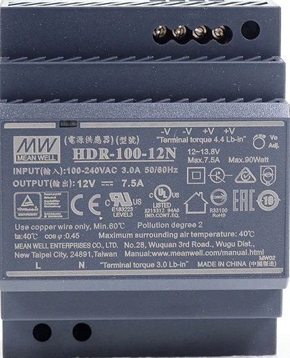
The Mean Well HDR-100-12N is a 100W, 12V DC power supply designed for industrial applications. It features a compact DIN-rail mountable design, high efficiency, and robust protections, making it ideal for powering industrial control systems, automation equipment, and other DC-powered devices. With its wide input voltage range and reliable performance, the HDR-100-12N is a versatile and durable solution for demanding environments.
Explore Projects Built with Mean Well HDR-100-12N
 Open Project in Cirkit Designer
 Open Project in Cirkit Designer
 Open Project in Cirkit Designer
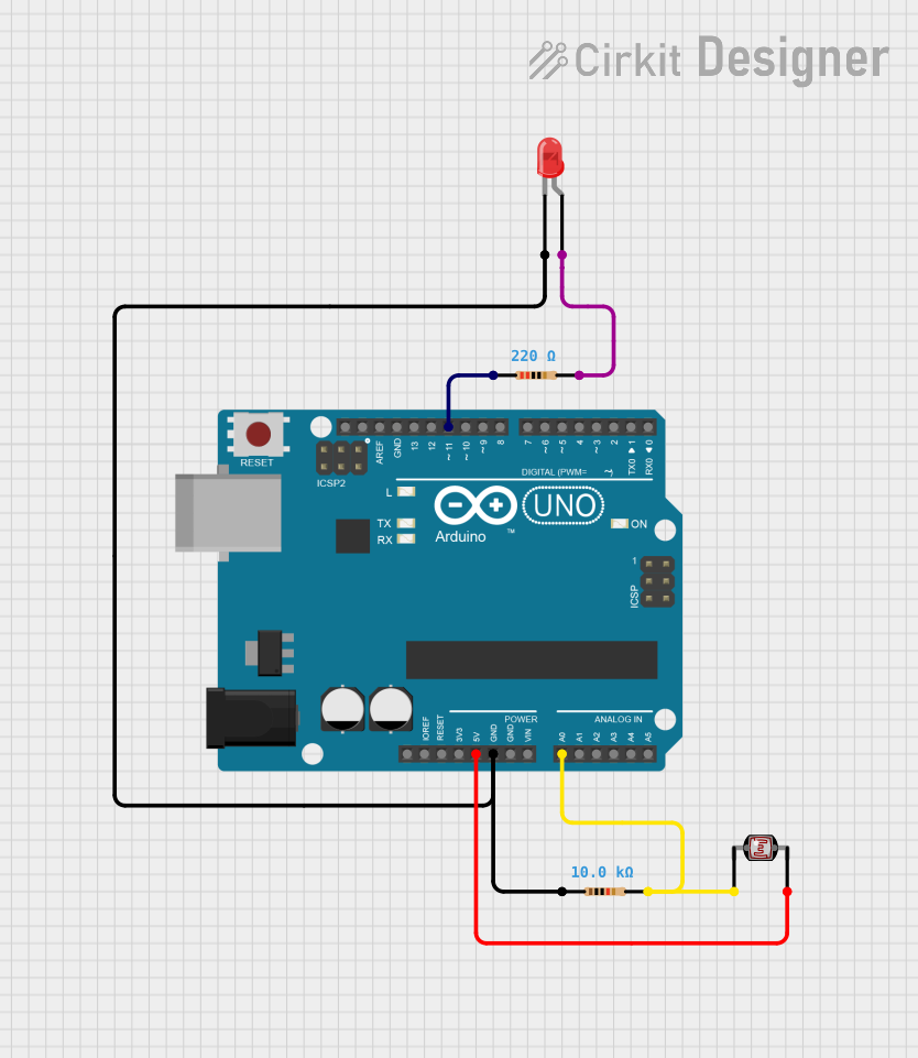 Open Project in Cirkit Designer
Explore Projects Built with Mean Well HDR-100-12N
Open Project in Cirkit DesignerOpen Project in Cirkit DesignerOpen Project in Cirkit DesignerOpen Project in Cirkit DesignerCommon Applications and Use Cases
- Industrial automation and control systems
- Building automation and HVAC systems
- LED lighting systems
- Security and surveillance equipment
- Test and measurement devices
Technical Specifications
Key Technical Details
| Parameter | Value |
|---|---|
| Input Voltage Range | 85-264 VAC / 120-370 VDC |
| Output Voltage | 12V DC |
| Output Current | 8.5A |
| Output Power | 102W |
| Efficiency | Up to 90% |
| Operating Temperature | -30°C to +70°C |
| Dimensions | 70mm x 90mm x 54mm |
| Mounting Type | DIN-rail (TS-35/7.5 or TS-35/15) |
| Protections | Overvoltage, Overcurrent, Short Circuit |
| Certifications | UL, CE, EAC, CB, RoHS |
Pin Configuration and Descriptions
The HDR-100-12N features screw terminal connections for input and output. Below is the pin configuration:
| Pin Number | Label | Description |
|---|---|---|
| 1 | L | AC Line Input |
| 2 | N | AC Neutral Input |
| 3 | Ground (⏚) | Earth Ground |
| 4 | +V | Positive DC Output |
| 5 | -V | Negative DC Output |
Usage Instructions
How to Use the HDR-100-12N in a Circuit
- Mounting: Secure the HDR-100-12N onto a DIN rail (TS-35/7.5 or TS-35/15) in your control panel or enclosure.
- Input Connection:
- Connect the AC line (L) and neutral (N) wires to the input terminals.
- Ensure the earth ground (⏚) is properly connected for safety.
- Output Connection:
- Connect the positive (+V) and negative (-V) terminals to your load or circuit.
- Verify that the load does not exceed the maximum output current of 8.5A.
- Power On:
- After verifying all connections, apply AC power to the input terminals.
- The power supply will regulate the output to 12V DC.
Important Considerations and Best Practices
- Input Voltage: Ensure the input voltage is within the specified range (85-264 VAC or 120-370 VDC).
- Load Requirements: Do not exceed the maximum output power of 102W or the current limit of 8.5A.
- Ventilation: Install the power supply in a well-ventilated area to prevent overheating.
- Wiring: Use appropriately rated wires for both input and output connections.
- Protections: The HDR-100-12N includes built-in protections for overvoltage, overcurrent, and short circuit. However, ensure proper circuit design to avoid unnecessary stress on the power supply.
Example: Connecting to an Arduino UNO
The HDR-100-12N can be used to power an Arduino UNO and other peripherals. Below is an example wiring setup:
- Connect the +V terminal of the HDR-100-12N to the VIN pin of the Arduino UNO.
- Connect the -V terminal of the HDR-100-12N to the GND pin of the Arduino UNO.
- Ensure the Arduino's input voltage requirements (7-12V) are met.
// Example Arduino code to blink an LED
// Ensure the HDR-100-12N is properly connected to the Arduino UNO

const int ledPin = 13; // Built-in LED pin on Arduino UNO

void setup() {
  pinMode(ledPin, OUTPUT); // Set the LED pin as an output
}

void loop() {
  digitalWrite(ledPin, HIGH); // Turn the LED on
  delay(1000);                // Wait for 1 second
  digitalWrite(ledPin, LOW);  // Turn the LED off
  delay(1000);                // Wait for 1 second
}
Troubleshooting and FAQs
Common Issues and Solutions
No Output Voltage:
- Verify that the input voltage is within the specified range.
- Check all connections for proper wiring.
- Ensure the load does not exceed the maximum output current.
Overheating:
- Ensure the power supply is installed in a well-ventilated area.
- Check for excessive load or short circuits in the output.
Intermittent Operation:
- Inspect the input voltage for stability.
- Verify that the load is not fluctuating beyond the power supply's capacity.
Output Voltage Too Low:
- Confirm that the load is not drawing more current than the rated 8.5A.
- Check for loose or corroded connections.
FAQs
Q: Can the HDR-100-12N be used outdoors?
A: The HDR-100-12N is not weatherproof and should be installed in a dry, indoor environment or within a weatherproof enclosure.
Q: What happens if the load exceeds 8.5A?
A: The power supply's overcurrent protection will activate, shutting down the output to prevent damage.
Q: Can I use the HDR-100-12N with a DC input?
A: Yes, the HDR-100-12N supports a DC input range of 120-370 VDC.
Q: Is the HDR-100-12N suitable for sensitive electronics?
A: Yes, the HDR-100-12N provides a stable 12V DC output, suitable for most sensitive electronics. However, additional filtering may be required for extremely noise-sensitive applications.