
How to Use Orange pi one: Examples, Pinouts, and Specs
 Design with Orange pi one in Cirkit Designer
Introduction
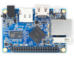
The Orange Pi One is a compact and versatile single-board computer (SBC) manufactured by Raspberry, with the part ID Pi 1. It is powered by an ARM Cortex-A7 processor and comes equipped with 512MB of RAM. This board is designed to support a variety of operating systems, including Android and Linux, making it an excellent choice for DIY electronics projects, media centers, and educational purposes.
The Orange Pi One also features General Purpose Input/Output (GPIO) pins, enabling users to interface with external hardware components such as sensors, motors, and displays. Its small size and affordability make it a popular choice for hobbyists and developers alike.
Explore Projects Built with Orange pi one
 Open Project in Cirkit Designer
 Open Project in Cirkit Designer
 Open Project in Cirkit Designer
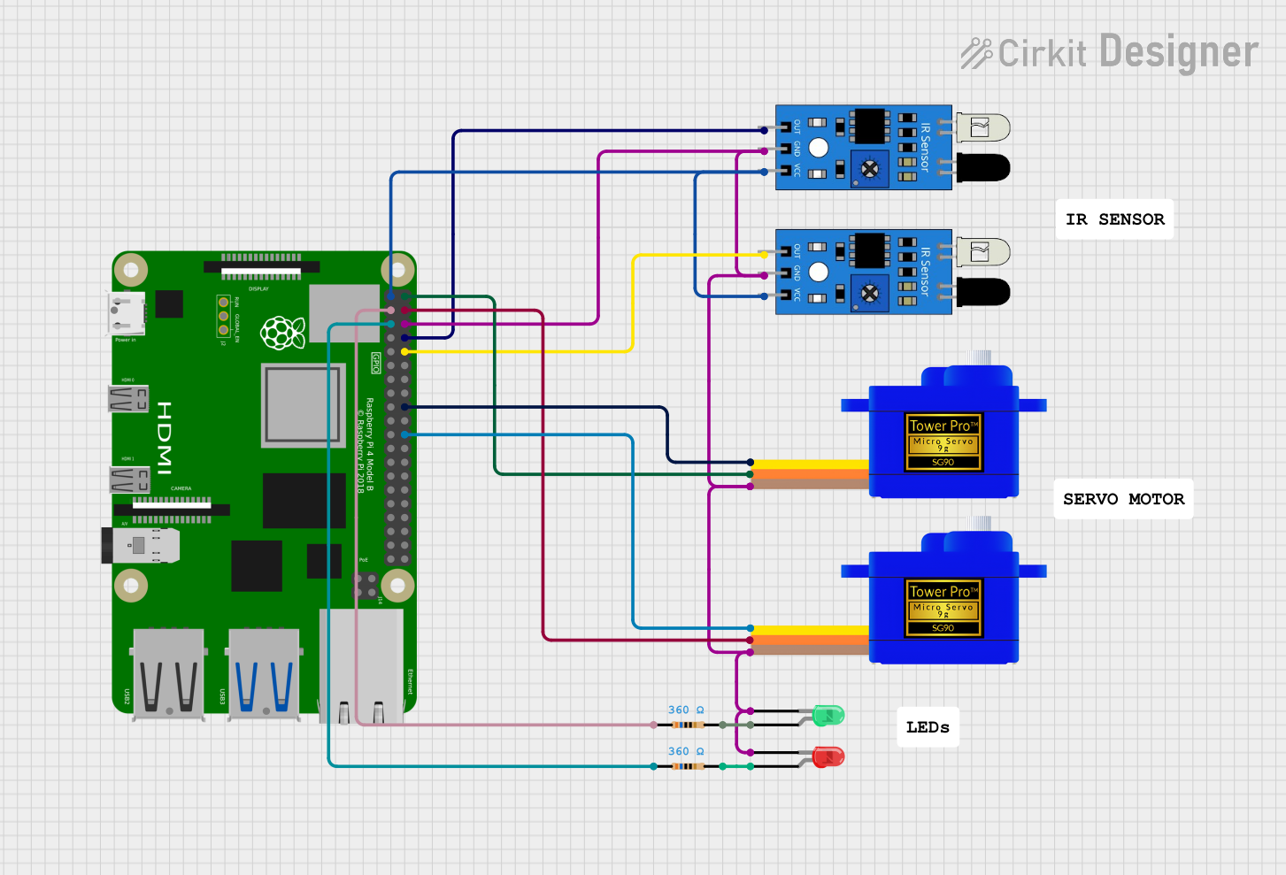 Open Project in Cirkit Designer
Explore Projects Built with Orange pi one
Open Project in Cirkit DesignerOpen Project in Cirkit DesignerOpen Project in Cirkit DesignerOpen Project in Cirkit DesignerCommon Applications
- DIY electronics projects
- Media centers and home automation
- Robotics and IoT (Internet of Things) applications
- Educational tools for learning programming and hardware interfacing
- Prototyping and development of embedded systems
Technical Specifications
Key Technical Details
| Specification | Value |
|---|---|
| Processor | ARM Cortex-A7 Quad-Core @ 1.2GHz |
| RAM | 512MB DDR3 |
| Storage | MicroSD card slot (up to 32GB supported) |
| Operating System Support | Android, Linux (e.g., Ubuntu, Debian) |
| GPIO Pins | 40-pin header |
| USB Ports | 1x USB 2.0, 1x Micro USB (power input) |
| Ethernet | 10/100Mbps Ethernet port |
| Video Output | HDMI (up to 1080p resolution) |
| Power Supply | 5V/2A via Micro USB |
| Dimensions | 69mm x 48mm |
Pin Configuration and Descriptions
The Orange Pi One features a 40-pin GPIO header, which is compatible with many Raspberry Pi accessories. Below is the pinout configuration:
| Pin Number | Pin Name | Description |
|---|---|---|
| 1 | 3.3V | Power supply (3.3V) |
| 2 | 5V | Power supply (5V) |
| 3 | GPIO2 (SDA) | I2C Data |
| 4 | 5V | Power supply (5V) |
| 5 | GPIO3 (SCL) | I2C Clock |
| 6 | GND | Ground |
| 7 | GPIO4 | General Purpose I/O |
| 8 | GPIO14 (TXD) | UART Transmit |
| 9 | GND | Ground |
| 10 | GPIO15 (RXD) | UART Receive |
| ... | ... | ... (Refer to full datasheet for more) |
Usage Instructions
How to Use the Orange Pi One in a Circuit
Powering the Board:
Connect a 5V/2A power supply to the Micro USB port. Ensure the power supply is stable to avoid damaging the board.Installing an Operating System:
- Download a compatible OS image (e.g., Ubuntu, Debian, or Android) from the official Orange Pi website.
- Use software like Balena Etcher to flash the OS image onto a MicroSD card.
- Insert the MicroSD card into the slot on the Orange Pi One and power on the board.
Connecting Peripherals:
- Use the HDMI port to connect the board to a monitor or TV.
- Attach a USB keyboard and mouse for input.
- For network connectivity, plug in an Ethernet cable or configure Wi-Fi (if using a USB Wi-Fi adapter).
Using GPIO Pins:
The GPIO pins can be used to interface with external components like LEDs, sensors, and motors. Below is an example of controlling an LED using Python.
Example: Blinking an LED with Python
This example assumes you are using the Orange Pi GPIO library.
Import the required library for GPIO control
import OPi.GPIO as GPIO import time
Set the GPIO mode to BOARD (physical pin numbering)
GPIO.setmode(GPIO.BOARD)
Define the pin number where the LED is connected
LED_PIN = 7
Set the pin as an output
GPIO.setup(LED_PIN, GPIO.OUT)
Blink the LED in a loop
try: while True: GPIO.output(LED_PIN, GPIO.HIGH) # Turn LED on time.sleep(1) # Wait for 1 second GPIO.output(LED_PIN, GPIO.LOW) # Turn LED off time.sleep(1) # Wait for 1 second except KeyboardInterrupt: # Clean up GPIO settings on exit GPIO.cleanup()
Important Considerations
- Always check the voltage and current ratings of connected components to avoid damage.
- Use a heatsink if running the board for extended periods or under heavy loads.
- Avoid shorting GPIO pins, as this can permanently damage the board.
Troubleshooting and FAQs
Common Issues and Solutions
The board does not power on:
- Ensure the power supply provides 5V/2A and is properly connected.
- Check the Micro USB cable for damage or poor quality.
No display on the monitor:
- Verify that the HDMI cable is securely connected.
- Ensure the monitor is set to the correct input source.
- Confirm that the OS image was correctly flashed onto the MicroSD card.
GPIO pins not working:
- Double-check the pin configuration and ensure the correct mode (input/output) is set in your code.
- Inspect the connected components for faults or incorrect wiring.
The board overheats:
- Attach a heatsink or fan to the processor.
- Ensure the board is placed in a well-ventilated area.
FAQs
Q: Can I use a Raspberry Pi case for the Orange Pi One?
A: Some Raspberry Pi cases may fit, but the port layout may differ. Use a case specifically designed for the Orange Pi One for the best fit.
Q: What is the maximum supported MicroSD card size?
A: The Orange Pi One supports MicroSD cards up to 32GB.
Q: Can I power the board using GPIO pins?
A: Yes, you can supply 5V directly to the 5V GPIO pin, but ensure the power source is stable and regulated.
Q: Does the Orange Pi One support Wi-Fi?
A: The board does not have built-in Wi-Fi, but you can use a USB Wi-Fi adapter for wireless connectivity.
This concludes the documentation for the Orange Pi One. For further details, refer to the official datasheet or community forums.