How to Use Arduino Mega & ESP8266: Examples, Pinouts, and Specs
Introduction
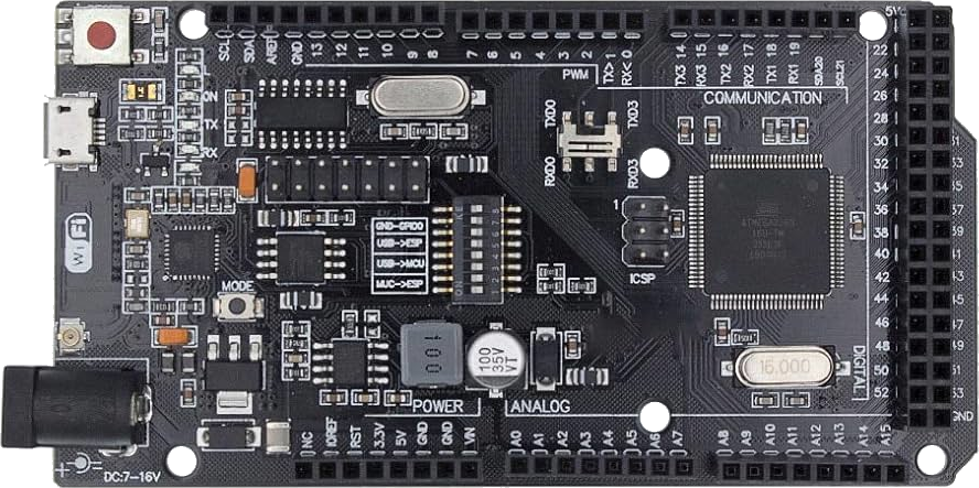
The Arduino Mega is a microcontroller board based on the ATmega2560, designed for projects requiring a large number of input/output pins and memory. The ESP8266 is a low-cost Wi-Fi module that enables wireless communication for IoT (Internet of Things) applications. When combined, the Arduino Mega and ESP8266 provide a powerful platform for creating connected devices with extensive I/O capabilities and wireless networking.
Explore Projects Built with Arduino Mega & ESP8266
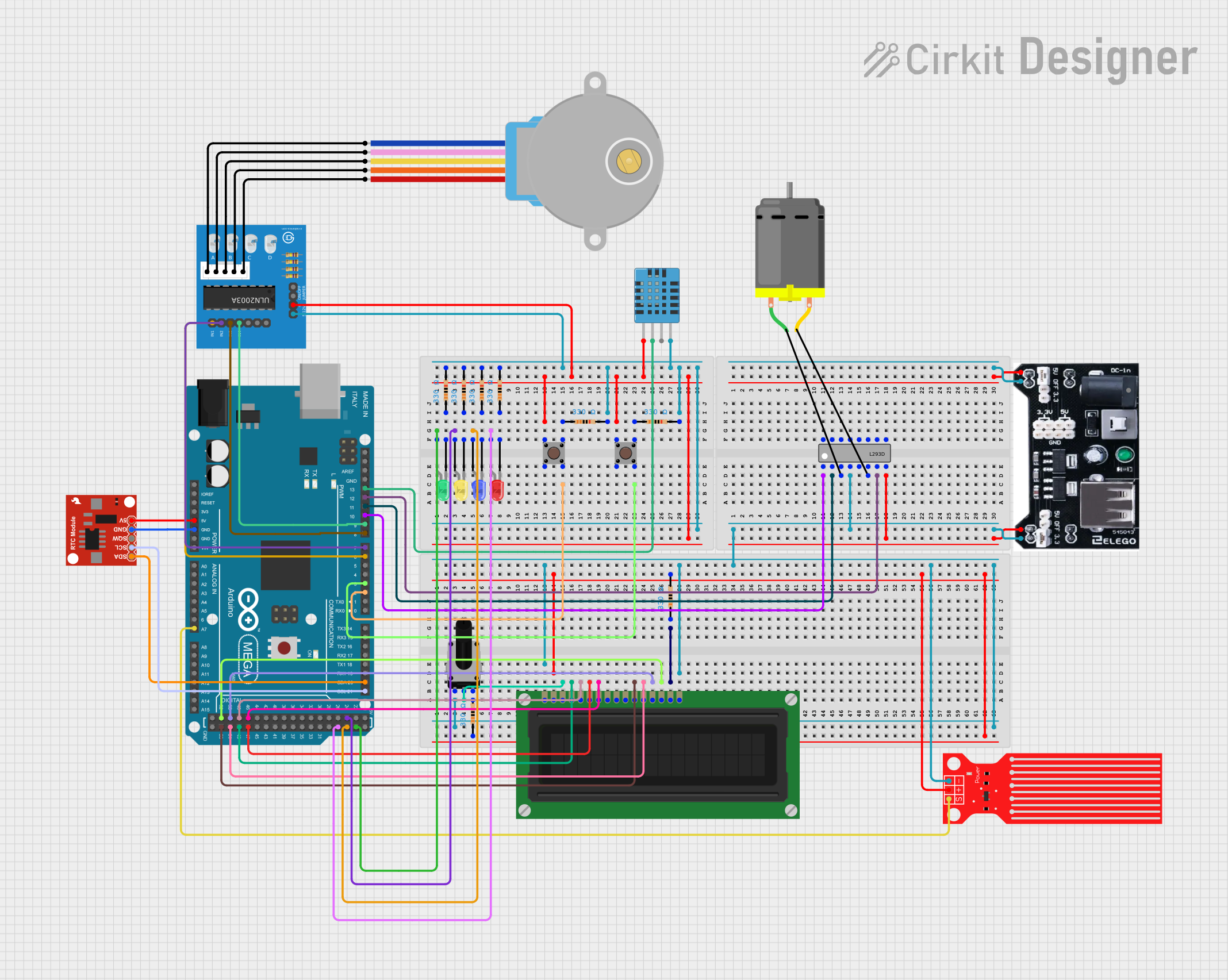
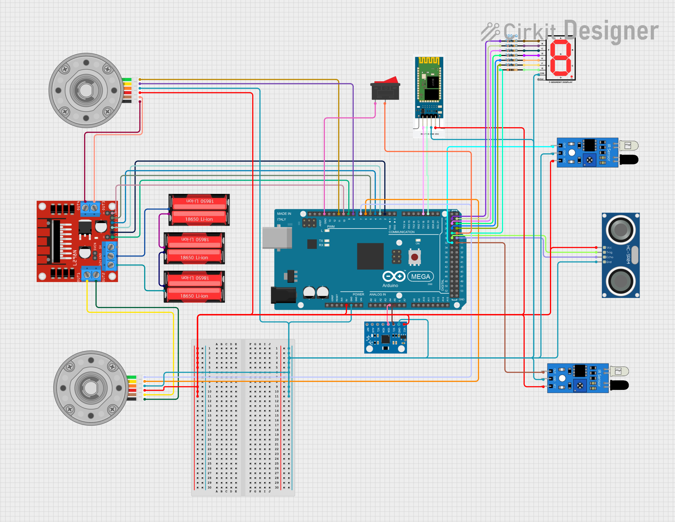
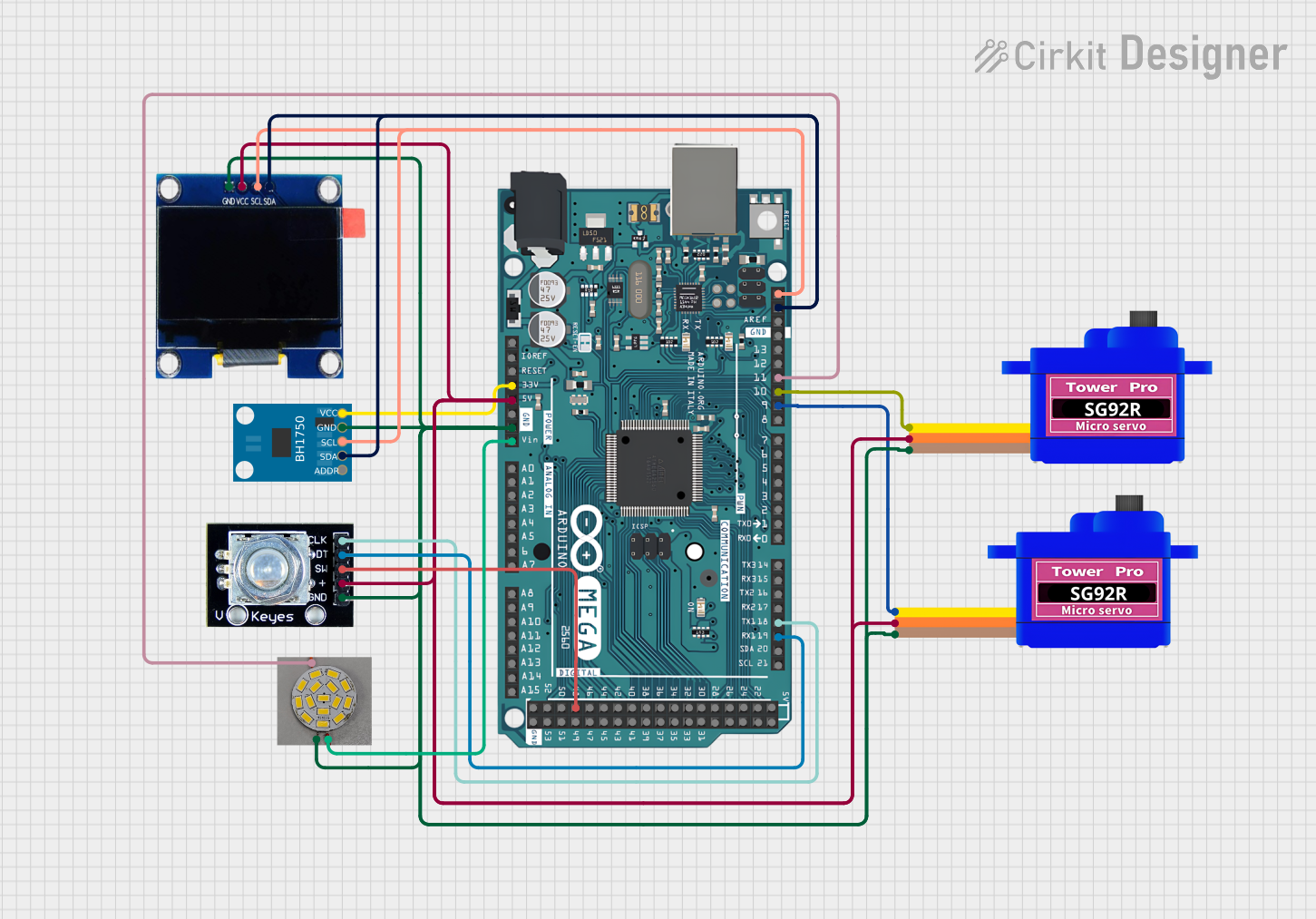
Explore Projects Built with Arduino Mega & ESP8266
Common Applications and Use Cases
- Home automation systems
- IoT devices and prototypes
- Wireless sensor networks
- Remote data logging and monitoring
- Smart appliances and robotics
Technical Specifications
Arduino Mega Specifications
| Parameter | Value |
|---|---|
| Microcontroller | ATmega2560 |
| Operating Voltage | 5V |
| Input Voltage (limits) | 6-20V |
| Digital I/O Pins | 54 (15 PWM outputs) |
| Analog Input Pins | 16 |
| Flash Memory | 256 KB (8 KB used by bootloader) |
| SRAM | 8 KB |
| EEPROM | 4 KB |
| Clock Speed | 16 MHz |
ESP8266 Specifications
| Parameter | Value |
|---|---|
| Microcontroller | Tensilica L106 32-bit RISC |
| Operating Voltage | 3.3V |
| Flash Memory | 1 MB to 16 MB (varies by model) |
| Wi-Fi Standards | 802.11 b/g/n |
| GPIO Pins | Up to 17 |
| Baud Rate | Default: 115200 |
| Power Consumption | 15 µA (deep sleep), ~70 mA (active) |
Pin Configuration and Descriptions
Arduino Mega Pinout
| Pin Number | Function | Description |
|---|---|---|
| 0-53 | Digital I/O | General-purpose digital pins |
| A0-A15 | Analog Input | Read analog signals (0-5V) |
| VIN | Input Voltage | External power supply input |
| GND | Ground | Common ground |
| 3.3V, 5V | Power Output | Regulated power output |
ESP8266 Pinout (Generic ESP-01 Module)
| Pin Name | Function | Description |
|---|---|---|
| VCC | Power Input | Connect to 3.3V |
| GND | Ground | Common ground |
| TX | UART Transmit | Serial data transmission |
| RX | UART Receive | Serial data reception |
| CH_PD | Chip Enable | Must be HIGH for normal operation |
| GPIO0 | General Purpose I/O | Used for programming or I/O |
| GPIO2 | General Purpose I/O | Used for I/O |
Usage Instructions
Connecting Arduino Mega to ESP8266
- Power Supply: Ensure the ESP8266 is powered with 3.3V. Do not connect it directly to the 5V pin of the Arduino Mega, as it may damage the module.
- Voltage Level Shifting: Use a voltage divider or level shifter for the TX pin of the Arduino Mega to step down the 5V signal to 3.3V for the ESP8266 RX pin.
- Wiring:
- Connect the ESP8266 TX pin to the Arduino Mega RX pin (e.g., Serial1 RX: Pin 19).
- Connect the ESP8266 RX pin to the Arduino Mega TX pin (e.g., Serial1 TX: Pin 18) through a level shifter.
- Connect the ESP8266 VCC and CH_PD pins to 3.3V.
- Connect the ESP8266 GND pin to the Arduino Mega GND.
Example Code for Communication
The following example demonstrates how to send AT commands to the ESP8266 from the Arduino Mega.
// Example: Communicating with ESP8266 using Arduino Mega
// Ensure the ESP8266 is connected to Serial1 (pins 18 and 19).

void setup() {
  Serial.begin(9600); // Initialize Serial Monitor for debugging
  Serial1.begin(115200); // Initialize Serial1 for ESP8266 communication

  Serial.println("Initializing ESP8266...");
  delay(2000); // Allow time for ESP8266 to boot

  // Send AT command to test communication
  Serial1.println("AT");
}

void loop() {
  // Check if data is available from ESP8266
  if (Serial1.available()) {
    String response = Serial1.readString(); // Read response from ESP8266
    Serial.println("ESP8266 Response: " + response); // Print response to Serial Monitor
  }

  // Check if user input is available from Serial Monitor
  if (Serial.available()) {
    String command = Serial.readString(); // Read user input
    Serial1.println(command); // Send command to ESP8266
  }
}
Important Considerations
- Power Supply: Use a stable 3.3V power source for the ESP8266. Avoid powering it directly from the Arduino Mega's 3.3V pin if the current demand exceeds 50 mA.
- Baud Rate: Ensure the baud rate of the ESP8266 matches the configuration in your code.
- Firmware: Verify that the ESP8266 firmware supports AT commands if using the module in AT mode.
Troubleshooting and FAQs
Common Issues
ESP8266 Not Responding to AT Commands:
- Ensure the ESP8266 is powered correctly (3.3V) and the CH_PD pin is HIGH.
- Check the baud rate configuration in your code and match it with the ESP8266's default baud rate.
Garbage Data in Serial Monitor:
- Verify that the Serial Monitor baud rate matches the
Serial.begin()configuration. - Ensure proper wiring and use of level shifters for the ESP8266 RX pin.
- Verify that the Serial Monitor baud rate matches the
ESP8266 Keeps Resetting:
- Check the power supply. Insufficient current can cause instability.
- Add a capacitor (e.g., 10 µF) across the VCC and GND pins of the ESP8266 to stabilize the power.
FAQs
Q: Can I use the Arduino Mega's 5V pin to power the ESP8266?
A: No, the ESP8266 operates at 3.3V. Using 5V can damage the module. Use a 3.3V regulator or a dedicated power supply.
Q: How do I update the ESP8266 firmware?
A: Use a USB-to-serial adapter and the ESP8266 Flash Download Tool. Ensure GPIO0 is pulled LOW during the flashing process.
Q: Can I use SoftwareSerial for communication with the ESP8266?
A: While possible, it is not recommended on the Arduino Mega due to its multiple hardware serial ports, which are more reliable and efficient.