How to Use DFRobot Motor Driver: Examples, Pinouts, and Specs
Introduction
The DFRobot Motor Driver, based on the TB6612FNG chip, is a compact and efficient motor driver module designed for controlling DC motors and stepper motors. It supports features such as speed control, direction control, and the ability to drive two motors simultaneously. This module is ideal for robotics, automation, and other motor control applications where precise and reliable operation is required.
Explore Projects Built with DFRobot Motor Driver


Explore Projects Built with DFRobot Motor Driver
Common Applications and Use Cases
- Robotics projects for driving wheels or actuators
- Automation systems requiring motorized components
- DIY projects involving DC or stepper motors
- Educational kits for learning motor control
- Prototyping motorized mechanisms
Technical Specifications
The DFRobot Motor Driver (TB6612FNG) has the following key specifications:
| Parameter | Value |
|---|---|
| Operating Voltage | 2.7V to 5.5V |
| Motor Drive Voltage | 4.5V to 13.5V |
| Continuous Output Current | 1.2A per channel (max) |
| Peak Output Current | 3.2A per channel (short duration) |
| PWM Frequency | Up to 100 kHz |
| Control Logic Voltage | 2.7V to 5.5V |
| Number of Channels | 2 (can drive 2 DC motors or 1 stepper motor) |
| Standby Current | 1 µA (typical) |
| Dimensions | 21mm x 18mm x 3mm |
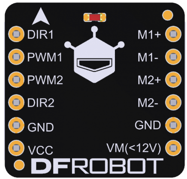
Pin Configuration and Descriptions
The TB6612FNG motor driver module has the following pinout:
| Pin Name | Type | Description |
|---|---|---|
| VCC | Power Input | Logic voltage input (2.7V to 5.5V). |
| VM | Power Input | Motor power supply (4.5V to 13.5V). |
| GND | Ground | Ground connection. |
| AIN1 | Input | Input signal for Motor A direction control. |
| AIN2 | Input | Input signal for Motor A direction control. |
| PWMA | Input (PWM) | PWM signal input for Motor A speed control. |
| BIN1 | Input | Input signal for Motor B direction control. |
| BIN2 | Input | Input signal for Motor B direction control. |
| PWMB | Input (PWM) | PWM signal input for Motor B speed control. |
| STBY | Input | Standby control pin. Set HIGH to enable the driver, LOW to disable. |
| AO1 | Output | Motor A output terminal 1. |
| AO2 | Output | Motor A output terminal 2. |
| BO1 | Output | Motor B output terminal 1. |
| BO2 | Output | Motor B output terminal 2. |
Usage Instructions
How to Use the Component in a Circuit
Power Connections:
- Connect the
VCCpin to a 3.3V or 5V logic power supply. - Connect the
VMpin to the motor power supply (4.5V to 13.5V). - Connect the
GNDpin to the ground of the power supply.
- Connect the
Motor Connections:
- Connect the motor terminals to
AO1andAO2for Motor A, andBO1andBO2for Motor B.
- Connect the motor terminals to
Control Connections:
- Use the
AIN1,AIN2, andPWMApins to control Motor A. - Use the
BIN1,BIN2, andPWMBpins to control Motor B. - Set the
STBYpin HIGH to enable the driver.
- Use the
Direction and Speed Control:
- Set the direction of the motor by configuring
AIN1andAIN2(orBIN1andBIN2). - Control the speed by providing a PWM signal to
PWMA(orPWMB).
- Set the direction of the motor by configuring
Important Considerations and Best Practices
- Ensure that the motor power supply voltage (
VM) matches the requirements of your motors. - Use appropriate decoupling capacitors near the power supply pins to reduce noise.
- Avoid exceeding the maximum current rating of 1.2A per channel to prevent damage.
- Use heat sinks or proper ventilation if operating at high currents for extended periods.
- Always set the
STBYpin LOW when the driver is not in use to minimize power consumption.
Example Code for Arduino UNO
Below is an example of how to control two DC motors using the DFRobot Motor Driver with an Arduino UNO:
// Define motor control pins
#define AIN1 7  // Motor A direction control pin 1
#define AIN2 8  // Motor A direction control pin 2
#define PWMA 9  // Motor A speed control (PWM) pin
#define BIN1 10 // Motor B direction control pin 1
#define BIN2 11 // Motor B direction control pin 2
#define PWMB 3  // Motor B speed control (PWM) pin
#define STBY 12 // Standby control pin

void setup() {
  // Set motor control pins as outputs
  pinMode(AIN1, OUTPUT);
  pinMode(AIN2, OUTPUT);
  pinMode(PWMA, OUTPUT);
  pinMode(BIN1, OUTPUT);
  pinMode(BIN2, OUTPUT);
  pinMode(PWMB, OUTPUT);
  pinMode(STBY, OUTPUT);

  // Enable the motor driver
  digitalWrite(STBY, HIGH);
}

void loop() {
  // Motor A: Forward at 50% speed
  digitalWrite(AIN1, HIGH);
  digitalWrite(AIN2, LOW);
  analogWrite(PWMA, 128); // 50% duty cycle (0-255)

  // Motor B: Reverse at 75% speed
  digitalWrite(BIN1, LOW);
  digitalWrite(BIN2, HIGH);
  analogWrite(PWMB, 192); // 75% duty cycle (0-255)

  delay(2000); // Run motors for 2 seconds

  // Stop both motors
  analogWrite(PWMA, 0);
  analogWrite(PWMB, 0);

  delay(2000); // Wait for 2 seconds
}
Troubleshooting and FAQs
Common Issues and Solutions
Motors Not Running:
- Ensure the
STBYpin is set HIGH to enable the driver. - Verify that the power supply connections (
VCC,VM, andGND) are correct. - Check the PWM signal and ensure it is within the supported frequency range.
- Ensure the
Motor Running in the Wrong Direction:
- Swap the
AIN1andAIN2(orBIN1andBIN2) signals to reverse the motor direction.
- Swap the
Overheating:
- Ensure the current drawn by the motors does not exceed 1.2A per channel.
- Use heat sinks or improve ventilation if necessary.
Noisy Operation:
- Add decoupling capacitors near the motor terminals to reduce electrical noise.
- Ensure proper grounding and minimize long wire runs.
FAQs
Q: Can I use this module to control a stepper motor?
A: Yes, the TB6612FNG can control a stepper motor by driving its two coils. You will need to generate the appropriate step sequences using the control pins.
Q: What is the maximum PWM frequency supported?
A: The module supports PWM frequencies up to 100 kHz.
Q: Can I use a 12V power supply for both VM and VCC?
A: No, VCC should be between 2.7V and 5.5V. Use a voltage regulator if your logic circuit requires 5V or 3.3V.