How to Use DY-SV17F: Examples, Pinouts, and Specs
Introduction
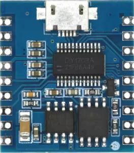
The DY-SV17F is a compact, low-power, high-performance RF transceiver module designed for wireless communication applications. Operating in the 433MHz frequency band, it is ideal for applications requiring reliable and efficient wireless data transmission. Its small form factor and low power consumption make it a popular choice for remote control systems, sensor networks, and IoT devices.
Explore Projects Built with DY-SV17F


Explore Projects Built with DY-SV17F
Common Applications
- Remote control systems (e.g., garage doors, drones, and home automation)
- Wireless sensor networks
- Internet of Things (IoT) devices
- Industrial automation and monitoring
- Wireless data logging systems
Technical Specifications
The DY-SV17F module is designed to deliver robust performance while maintaining low power consumption. Below are its key technical specifications:
| Parameter | Value |
|---|---|
| Operating Frequency | 433 MHz |
| Modulation Type | FSK/ASK |
| Operating Voltage | 2.0V - 3.6V |
| Operating Current | < 15 mA (transmit mode) |
| Sleep Current | < 1 µA |
| Data Rate | Up to 250 kbps |
| Communication Range | Up to 300 meters (line of sight) |
| Operating Temperature | -40°C to +85°C |
| Dimensions | 15mm x 15mm x 3mm |
Pin Configuration and Descriptions
The DY-SV17F module has a simple pinout, making it easy to integrate into various designs. Below is the pin configuration:
| Pin Number | Pin Name | Description |
|---|---|---|
| 1 | VCC | Power supply input (2.0V - 3.6V) |
| 2 | GND | Ground |
| 3 | TXD | Transmit data pin (UART interface) |
| 4 | RXD | Receive data pin (UART interface) |
| 5 | ANT | Antenna connection for RF signal transmission |
| 6 | EN | Enable pin (active HIGH to enable the module) |
Usage Instructions
The DY-SV17F module is straightforward to use in wireless communication systems. Below are the steps and best practices for integrating it into your project:
Basic Circuit Connection
- Power Supply: Connect the VCC pin to a regulated 3.3V power source and the GND pin to the ground.
- UART Communication: Connect the TXD pin of the module to the RX pin of your microcontroller and the RXD pin of the module to the TX pin of your microcontroller.
- Antenna: Attach a 433MHz antenna to the ANT pin for optimal signal transmission and reception.
- Enable Pin: Pull the EN pin HIGH to activate the module. If unused, connect it to VCC.
Important Considerations
- Use a decoupling capacitor (e.g., 0.1µF) between VCC and GND to reduce noise and ensure stable operation.
- Ensure the antenna is properly matched to the 433MHz frequency band for maximum range and performance.
- Avoid placing the module near high-frequency noise sources or metal enclosures that may interfere with RF signals.
Example: Using DY-SV17F with Arduino UNO
The DY-SV17F can be easily interfaced with an Arduino UNO using its UART interface. Below is an example code snippet to send and receive data:
// Example code to interface DY-SV17F with Arduino UNO
// This code sends and receives data via the DY-SV17F module

#include <SoftwareSerial.h>

// Define RX and TX pins for SoftwareSerial
SoftwareSerial DY_Serial(10, 11); // RX = Pin 10, TX = Pin 11

void setup() {
  // Initialize serial communication
  Serial.begin(9600);            // Serial monitor communication
  DY_Serial.begin(9600);         // DY-SV17F communication

  Serial.println("DY-SV17F Module Initialized");
}

void loop() {
  // Send data to DY-SV17F
  DY_Serial.println("Hello, DY-SV17F!");

  // Check if data is available from DY-SV17F
  if (DY_Serial.available()) {
    String receivedData = DY_Serial.readString(); // Read incoming data
    Serial.print("Received: ");
    Serial.println(receivedData);                // Print received data
  }

  delay(1000); // Wait for 1 second
}
Notes:
- Replace
10and11with the appropriate pins if using different connections. - Ensure the baud rate (9600 in this example) matches the module's default UART settings.
Troubleshooting and FAQs
Common Issues and Solutions
No Communication with the Module
- Cause: Incorrect wiring or baud rate mismatch.
- Solution: Double-check the connections and ensure the UART baud rate matches the module's settings.
Short Communication Range
- Cause: Poor antenna connection or interference.
- Solution: Verify the antenna is securely connected and properly tuned for 433MHz. Avoid placing the module near metal objects or sources of RF interference.
High Power Consumption
- Cause: Module not entering sleep mode.
- Solution: Ensure the EN pin is properly controlled to enable/disable the module as needed.
Data Loss or Corruption
- Cause: High data rate or noisy environment.
- Solution: Reduce the data rate and use error-checking mechanisms in your communication protocol.
FAQs
Q: Can the DY-SV17F operate at frequencies other than 433MHz?
A: No, the DY-SV17F is specifically designed for the 433MHz frequency band.
Q: What is the maximum communication range of the DY-SV17F?
A: The module can achieve a range of up to 300 meters in line-of-sight conditions. Obstacles and interference may reduce this range.
Q: Is the DY-SV17F compatible with 5V systems?
A: The module operates at 2.0V - 3.6V. Use a level shifter or voltage divider to interface with 5V systems.
Q: Can I use the DY-SV17F for bidirectional communication?
A: Yes, the module supports bidirectional communication via its UART interface.
By following the guidelines and best practices outlined in this documentation, you can effectively integrate the DY-SV17F module into your wireless communication projects.