
How to Use DSPIC30F6015: Examples, Pinouts, and Specs

 Design with DSPIC30F6015 in Cirkit Designer
Introduction
The DSPIC30F6015 is a 16-bit Digital Signal Controller (DSC) from Microchip Technology, designed to combine the performance of a Digital Signal Processor (DSP) with the simplicity of a microcontroller. It is ideal for high-performance applications requiring real-time control, signal processing, and advanced communication capabilities. With its integrated DSP engine, multiple I/O ports, and support for various communication protocols, the DSPIC30F6015 is a versatile solution for a wide range of embedded systems.
Explore Projects Built with DSPIC30F6015
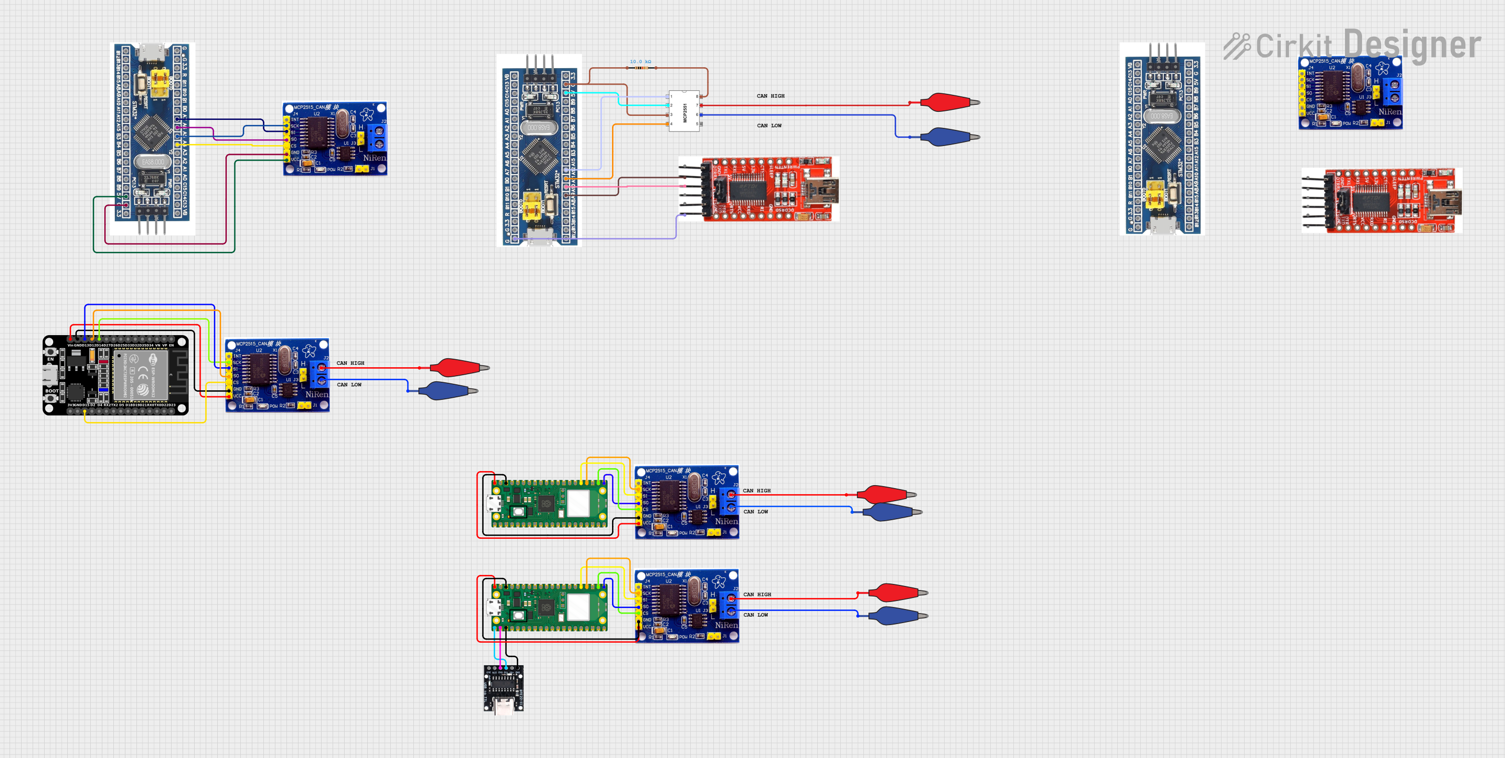 Open Project in Cirkit Designer
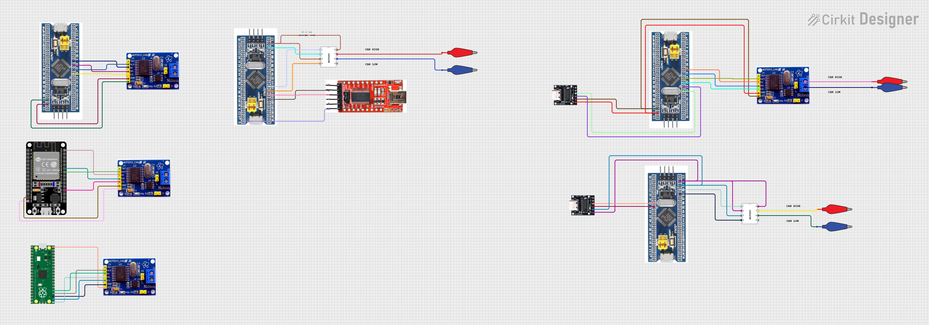 Open Project in Cirkit Designer
 Open Project in Cirkit Designer
 Open Project in Cirkit Designer
Explore Projects Built with DSPIC30F6015
Open Project in Cirkit DesignerOpen Project in Cirkit DesignerOpen Project in Cirkit DesignerOpen Project in Cirkit DesignerCommon Applications and Use Cases
- Motor control and power conversion systems
- Audio and speech processing
- Industrial automation and control
- Medical devices
- Communication systems
- Embedded signal processing
Technical Specifications
The DSPIC30F6015 offers a robust set of features and specifications to meet the demands of complex applications. Below are the key technical details:
General Specifications
| Parameter | Value |
|---|---|
| Core Architecture | 16-bit Digital Signal Controller (DSC) |
| Operating Voltage | 2.5V to 5.5V |
| Maximum Clock Speed | 30 MIPS |
| Program Memory (Flash) | 144 KB |
| Data Memory (RAM) | 8 KB |
| EEPROM | 4 KB |
| Operating Temperature Range | -40°C to +125°C |
Peripherals and Features
| Feature | Description |
|---|---|
| DSP Engine | 16x16 Multiply-Accumulate (MAC) unit, barrel shifter |
| Timers | 5 x 16-bit timers |
| PWM Modules | 6 PWM channels with dead-time control |
| ADC | 16-channel, 10-bit ADC |
| Communication Interfaces | UART, SPI, I2C, CAN |
| I/O Ports | Multiple GPIO pins with interrupt-on-change |
| Watchdog Timer | Programmable with on-chip oscillator |
Pin Configuration and Descriptions
The DSPIC30F6015 is available in multiple packages, such as 64-pin TQFP and 80-pin TQFP. Below is an example of the pin configuration for the 64-pin TQFP package:
| Pin Number | Pin Name | Description |
|---|---|---|
| 1 | VDD | Positive supply voltage |
| 2 | VSS | Ground |
| 3 | AN0 | Analog input channel 0 |
| 4 | AN1 | Analog input channel 1 |
| 5 | PWM1H | PWM output 1 high |
| 6 | PWM1L | PWM output 1 low |
| 7 | RX1 | UART1 receive |
| 8 | TX1 | UART1 transmit |
| ... | ... | ... (Refer to the datasheet for full details) |
Usage Instructions
How to Use the DSPIC30F6015 in a Circuit
- Power Supply: Ensure the supply voltage is within the range of 2.5V to 5.5V. Use decoupling capacitors (e.g., 0.1 µF) near the VDD and VSS pins to reduce noise.
- Clock Configuration: Connect an external crystal oscillator or use the internal oscillator for clock generation. Configure the clock settings in the firmware.
- Programming: Use a compatible programmer/debugger, such as the Microchip ICD3 or PICkit, to program the device via the ICSP (In-Circuit Serial Programming) pins.
- Peripheral Configuration: Initialize the required peripherals (e.g., ADC, UART, PWM) in the firmware based on your application.
- GPIO Usage: Configure the GPIO pins as input or output as needed. Use pull-up or pull-down resistors for unused pins to avoid floating states.
Important Considerations and Best Practices
- Signal Integrity: Keep analog and digital signal traces separate to minimize noise interference.
- Power Management: Use proper decoupling and filtering techniques to ensure stable operation.
- Programming Safety: Verify the configuration bits before programming to avoid unintended behavior.
- Thermal Management: Ensure adequate cooling if the device operates near its maximum temperature range.
Example: Interfacing DSPIC30F6015 with an Arduino UNO
The DSPIC30F6015 can communicate with an Arduino UNO via UART. Below is an example Arduino sketch to send data to the DSPIC30F6015:
// Arduino UNO UART Communication with DSPIC30F6015
// This code sends a message to the DSPIC30F6015 via UART.

void setup() {
  Serial.begin(9600); // Initialize UART at 9600 baud rate
  delay(1000);        // Wait for the DSPIC30F6015 to initialize
}

void loop() {
  Serial.println("Hello, DSPIC30F6015!"); // Send data to DSPIC30F6015
  delay(1000);                           // Wait 1 second before sending again
}
On the DSPIC30F6015 side, configure the UART module to receive data at 9600 baud and process the incoming message.
Troubleshooting and FAQs
Common Issues and Solutions
Device Not Responding
- Cause: Incorrect power supply or clock configuration.
- Solution: Verify the supply voltage and clock settings. Check for proper connections.
Programming Failure
- Cause: Faulty programmer or incorrect ICSP connections.
- Solution: Ensure the programmer is functioning correctly and the ICSP pins are properly connected.
Peripheral Not Working
- Cause: Incorrect initialization or configuration.
- Solution: Double-check the peripheral initialization code and ensure the correct pins are used.
Excessive Noise in ADC Readings
- Cause: Poor PCB layout or insufficient decoupling.
- Solution: Improve PCB layout by separating analog and digital traces. Add decoupling capacitors near the ADC pins.
FAQs
Q1: Can the DSPIC30F6015 operate without an external oscillator?
A1: Yes, the DSPIC30F6015 has an internal oscillator that can be used, but an external oscillator is recommended for applications requiring precise timing.
Q2: How do I debug my code on the DSPIC30F6015?
A2: Use a compatible debugger, such as the Microchip ICD3 or MPLAB REAL ICE, and configure the debugging settings in MPLAB X IDE.
Q3: What is the maximum PWM resolution of the DSPIC30F6015?
A3: The PWM resolution depends on the clock frequency and timer settings. Refer to the datasheet for detailed calculations.
Q4: Can I use the DSPIC30F6015 for motor control applications?
A4: Yes, the DSPIC30F6015 is well-suited for motor control applications due to its integrated PWM modules and DSP capabilities.