
How to Use SCC PWM: Examples, Pinouts, and Specs
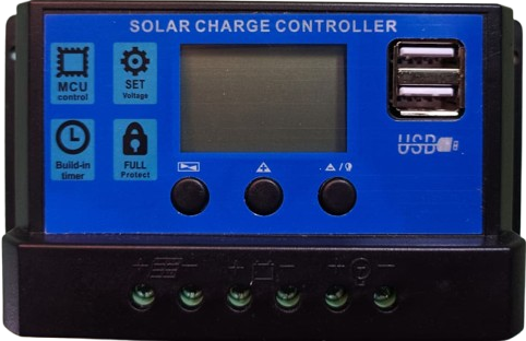
 Design with SCC PWM in Cirkit Designer
Introduction
The Switching Control Circuit Pulse Width Modulator (SCC PWM) is an electronic component designed to regulate the power delivered to electrical devices by adjusting the width of pulses in a pulse train. This modulation technique enables efficient energy management, making it ideal for applications requiring precise control of power delivery. SCC PWM is commonly used in motor control, LED dimming, power supplies, and other systems where energy efficiency and control are critical.
Explore Projects Built with SCC PWM
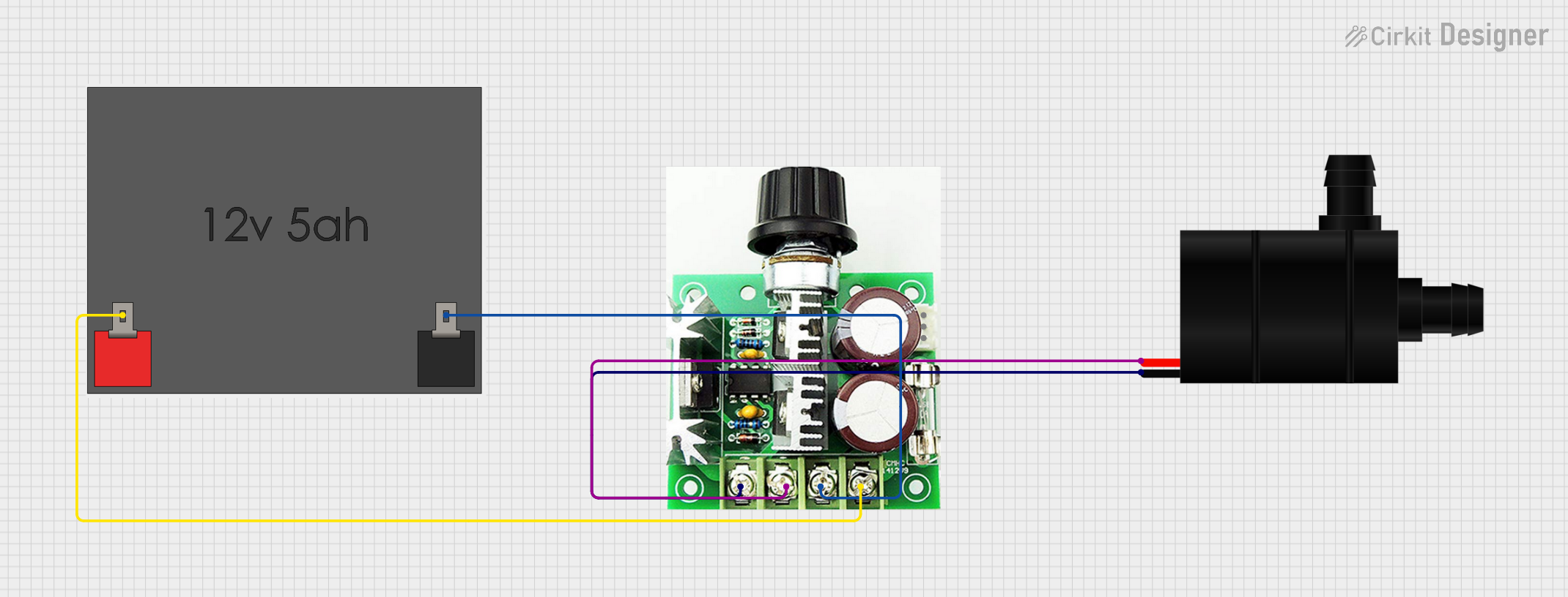 Open Project in Cirkit Designer
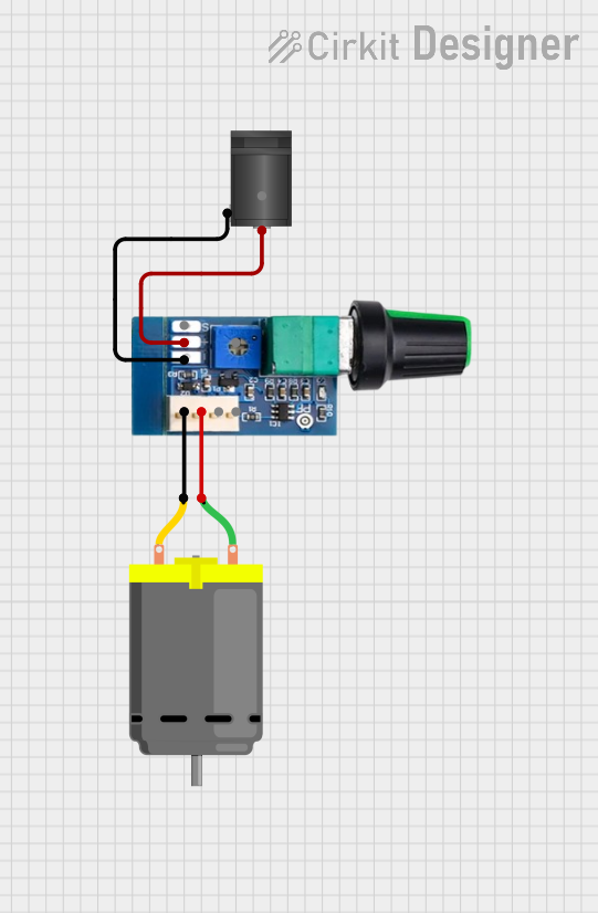 Open Project in Cirkit Designer
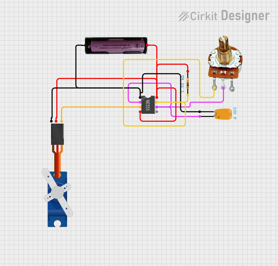 Open Project in Cirkit Designer
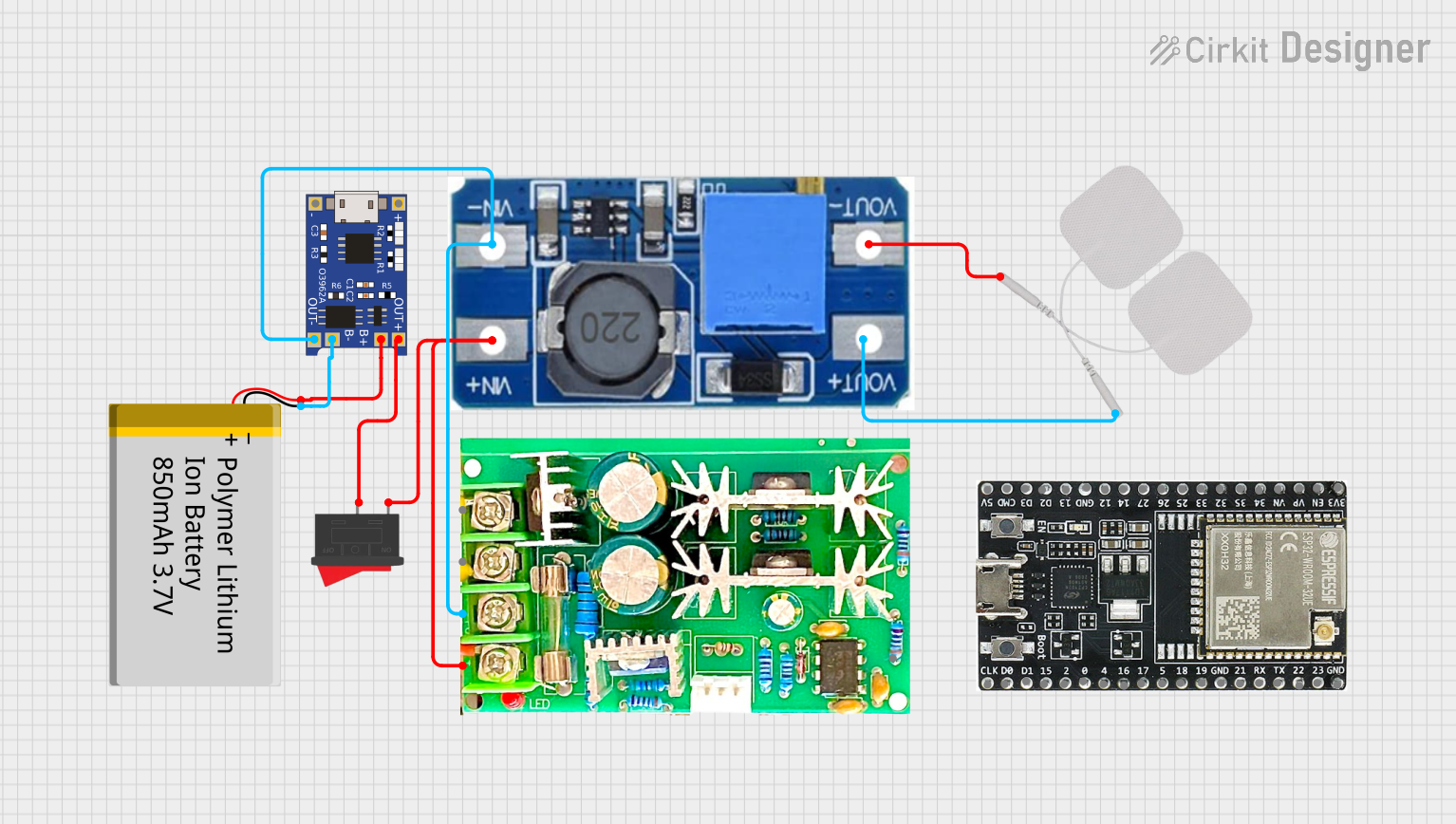 Open Project in Cirkit Designer
Explore Projects Built with SCC PWM
Open Project in Cirkit DesignerOpen Project in Cirkit DesignerOpen Project in Cirkit DesignerOpen Project in Cirkit DesignerCommon Applications:
- Motor speed control in industrial and consumer devices
- LED brightness adjustment
- Voltage regulation in power supplies
- Heating element control in temperature management systems
Technical Specifications
Below are the key technical details and pin configuration for the SCC PWM:
Key Technical Details:
| Parameter | Value |
|---|---|
| Input Voltage Range | 4.5V to 40V |
| Output Voltage Range | 0V to Input Voltage |
| Output Current | Up to 2A |
| Frequency Range | 1 kHz to 100 kHz |
| Duty Cycle Range | 0% to 100% |
| Efficiency | Up to 95% |
| Operating Temperature | -40°C to +85°C |
| Package Type | DIP-8 or SOIC-8 |
Pin Configuration:
| Pin Number | Pin Name | Description |
|---|---|---|
| 1 | VCC | Power supply input (4.5V to 40V) |
| 2 | GND | Ground connection |
| 3 | PWM_IN | Input for external PWM signal |
| 4 | FB | Feedback pin for voltage regulation |
| 5 | OUT | PWM output to the load |
| 6 | EN | Enable pin (active high) |
| 7 | COMP | Compensation pin for stability adjustment |
| 8 | NC | No connection (leave unconnected or grounded) |
Usage Instructions
How to Use the SCC PWM in a Circuit:
- Power Supply Connection: Connect the VCC pin to a DC power source within the specified input voltage range (4.5V to 40V). Connect the GND pin to the ground of the circuit.
- PWM Input: Provide a PWM signal to the PWM_IN pin. This signal determines the duty cycle of the output.
- Load Connection: Connect the load (e.g., motor, LED, or heating element) to the OUT pin. Ensure the load does not exceed the maximum output current rating (2A).
- Feedback and Stability: Use the FB and COMP pins to fine-tune the output voltage and ensure stability in the circuit. Refer to the component datasheet for recommended resistor and capacitor values.
- Enable Functionality: Use the EN pin to enable or disable the SCC PWM. Pull the pin high to enable the circuit or low to disable it.
Important Considerations:
- Heat Dissipation: Ensure proper heat dissipation for high-current applications. Use a heatsink or place the component in a well-ventilated area.
- Input Voltage: Do not exceed the maximum input voltage of 40V to avoid damaging the component.
- Filtering: Add decoupling capacitors near the VCC and GND pins to reduce noise and improve stability.
- Load Compatibility: Verify that the load is compatible with the output voltage and current ratings of the SCC PWM.
Example: Using SCC PWM with Arduino UNO
The SCC PWM can be controlled using an Arduino UNO to generate a PWM signal. Below is an example code to control the duty cycle of the SCC PWM:
// Example: Controlling SCC PWM with Arduino UNO
// This code generates a PWM signal on pin 9 to control the SCC PWM's output.

const int pwmPin = 9; // PWM output pin connected to SCC PWM's PWM_IN pin
int dutyCycle = 128;  // Initial duty cycle (50% of 255)

void setup() {
  pinMode(pwmPin, OUTPUT); // Set pin 9 as an output
}

void loop() {
  analogWrite(pwmPin, dutyCycle); // Write the duty cycle to the PWM pin
  delay(1000); // Wait for 1 second

  // Increase duty cycle by 10% (25.5 units) every second
  dutyCycle += 25;
  if (dutyCycle > 255) {
    dutyCycle = 0; // Reset duty cycle to 0% after reaching 100%
  }
}
Notes:
- Connect the Arduino's GND to the SCC PWM's GND to ensure a common ground.
- Adjust the
dutyCyclevariable to control the output power delivered to the load.
Troubleshooting and FAQs
Common Issues and Solutions:
No Output from SCC PWM:
- Ensure the EN pin is pulled high to enable the circuit.
- Verify that the input voltage is within the specified range (4.5V to 40V).
- Check the PWM_IN pin for a valid PWM signal.
Overheating:
- Ensure the load does not exceed the maximum output current (2A).
- Use a heatsink or improve ventilation around the component.
Unstable Output:
- Add decoupling capacitors near the VCC and GND pins.
- Adjust the compensation network connected to the COMP pin.
Load Not Responding:
- Verify the load's compatibility with the SCC PWM's output voltage and current.
- Check all connections for proper wiring.
FAQs:
Q: Can the SCC PWM operate without an external PWM signal?
A: No, the SCC PWM requires a valid PWM signal at the PWM_IN pin to modulate the output.
Q: What is the maximum frequency of the PWM signal?
A: The SCC PWM supports PWM frequencies up to 100 kHz.
Q: Can I use the SCC PWM for AC loads?
A: No, the SCC PWM is designed for DC loads only. For AC loads, use an appropriate AC controller.
Q: How do I calculate the required feedback resistor values?
A: Refer to the component datasheet for detailed formulas and recommended resistor values based on your desired output voltage.
By following this documentation, users can effectively integrate the SCC PWM into their projects for efficient power control and management.