
How to Use LT3045: Examples, Pinouts, and Specs
 Design with LT3045 in Cirkit Designer
Introduction
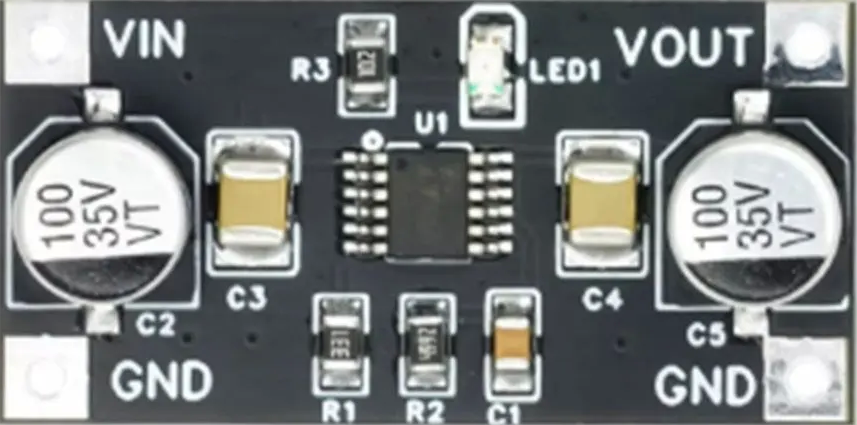
The LT3045 is a high-performance, low noise, low dropout linear voltage regulator designed to deliver a stable and precise output voltage. It features an impressive power supply rejection ratio (PSRR), making it ideal for noise-sensitive applications. With its wide input voltage range, low quiescent current, and excellent thermal performance, the LT3045 is well-suited for high-precision analog circuits, RF systems, medical devices, and test equipment.
Explore Projects Built with LT3045
 Open Project in Cirkit Designer
 Open Project in Cirkit Designer
 Open Project in Cirkit Designer
 Open Project in Cirkit Designer
Explore Projects Built with LT3045
Open Project in Cirkit DesignerOpen Project in Cirkit DesignerOpen Project in Cirkit DesignerOpen Project in Cirkit DesignerCommon Applications
- High-precision analog circuits
- RF and communication systems
- Medical instrumentation
- Test and measurement equipment
- Low-noise power supplies for sensitive devices
Technical Specifications
The LT3045 offers robust performance and flexibility. Below are its key technical specifications:
| Parameter | Value |
|---|---|
| Input Voltage Range | 2.8V to 20V |
| Output Voltage Range | 0V to 15V (adjustable) |
| Maximum Output Current | 500mA |
| Dropout Voltage | 260mV at 500mA |
| Output Voltage Noise | 0.8µVRMS (10Hz to 100kHz) |
| Power Supply Rejection Ratio | 79dB at 1MHz |
| Quiescent Current | 2.5mA (typical) |
| Operating Temperature Range | -40°C to 125°C |
| Package Options | DFN (10-lead), MSOP (10-lead) |
Pin Configuration and Descriptions
The LT3045 is available in a 10-lead DFN or MSOP package. Below is the pin configuration and description:
| Pin Number | Pin Name | Description |
|---|---|---|
| 1 | IN | Input voltage pin. Connect to the input power supply. |
| 2 | OUT | Regulated output voltage pin. Connect to the load. |
| 3 | SET | Voltage set pin. Connect a resistor to ground to set the output voltage. |
| 4 | GND | Ground pin. Connect to system ground. |
| 5 | BYP | Bypass pin. Connect a capacitor to reduce output noise. |
| 6 | ILIM | Current limit pin. Connect a resistor to set the current limit. |
| 7 | PG | Power good pin. Indicates when the output voltage is in regulation. |
| 8 | NC | No connection. Leave this pin unconnected. |
| 9 | SHDN | Shutdown pin. Pull low to disable the regulator. |
| 10 | NC | No connection. Leave this pin unconnected. |
Usage Instructions
How to Use the LT3045 in a Circuit
Input and Output Capacitors:
- Connect a low-ESR capacitor (e.g., 10µF ceramic) close to the IN pin to stabilize the input voltage.
- Similarly, connect a low-ESR capacitor (e.g., 10µF ceramic) close to the OUT pin for stable output voltage.
Setting the Output Voltage:
- Use a resistor (RSET) between the SET pin and ground to configure the output voltage.
- The output voltage is determined by the formula:
[ V_{OUT} = I_{SET} \times R_{SET} ]
where ( I_{SET} = 100\mu A ).
Bypass Capacitor:
- To minimize output noise, connect a capacitor (e.g., 10nF) between the BYP pin and ground.
Current Limit:
- Use a resistor (RLIM) between the ILIM pin and ground to set the current limit.
- The current limit is determined by the formula:
[ I_{LIMIT} = \frac{1.2V}{R_{LIM}} ]
Power Good Signal:
- The PG pin provides a logic signal indicating whether the output voltage is within regulation.
- Use this pin to monitor the regulator's status.
Shutdown Control:
- Pull the SHDN pin low to disable the regulator. Leave it floating or pull it high to enable the regulator.
Example Circuit with Arduino UNO
The LT3045 can be used to provide a clean 5V supply for an Arduino UNO. Below is an example circuit and Arduino code:
Circuit Description
- Connect a 12V DC power supply to the IN pin of the LT3045.
- Set the output voltage to 5V by choosing ( R_{SET} = 50k\Omega ).
- Connect the OUT pin to the Arduino UNO's 5V pin.
- Use a 10µF capacitor on both the IN and OUT pins for stability.
Arduino Code
// Example code to read an analog sensor using the LT3045 as a power supply
// The LT3045 provides a clean 5V output to power the Arduino UNO and sensor.

const int sensorPin = A0; // Analog pin connected to the sensor
int sensorValue = 0;      // Variable to store the sensor reading

void setup() {
  Serial.begin(9600); // Initialize serial communication at 9600 baud
}

void loop() {
  sensorValue = analogRead(sensorPin); // Read the sensor value
  Serial.print("Sensor Value: ");
  Serial.println(sensorValue); // Print the sensor value to the Serial Monitor
  delay(1000); // Wait for 1 second before the next reading
}
Important Considerations
- Ensure proper heat dissipation by using a heatsink or adequate PCB thermal design, especially at high currents.
- Use low-ESR capacitors for optimal performance.
- Avoid exceeding the maximum input voltage (20V) or output current (500mA) to prevent damage.
Troubleshooting and FAQs
Common Issues and Solutions
Output Voltage is Incorrect:
- Verify the RSET value and ensure it is correctly calculated for the desired output voltage.
- Check for loose or incorrect connections on the SET pin.
Regulator Overheating:
- Ensure proper thermal management by using a heatsink or improving PCB layout.
- Check if the input voltage and output current are within the specified limits.
No Output Voltage:
- Confirm that the SHDN pin is not pulled low.
- Check the input voltage and ensure it is within the specified range.
- Verify that the input and output capacitors are properly connected.
High Output Noise:
- Ensure a bypass capacitor is connected to the BYP pin.
- Use low-ESR capacitors on the input and output pins.
FAQs
Q: Can the LT3045 be used for negative voltage regulation?
A: No, the LT3045 is designed for positive voltage regulation only.
Q: What is the maximum output current of the LT3045?
A: The LT3045 can supply a maximum output current of 500mA.
Q: How can I reduce output noise further?
A: Use a high-quality bypass capacitor (e.g., 10nF ceramic) on the BYP pin and ensure proper PCB layout to minimize noise coupling.
Q: Is the LT3045 suitable for battery-powered applications?
A: Yes, its low quiescent current makes it ideal for battery-powered devices.