How to Use Condenser Microphone: Examples, Pinouts, and Specs
Introduction
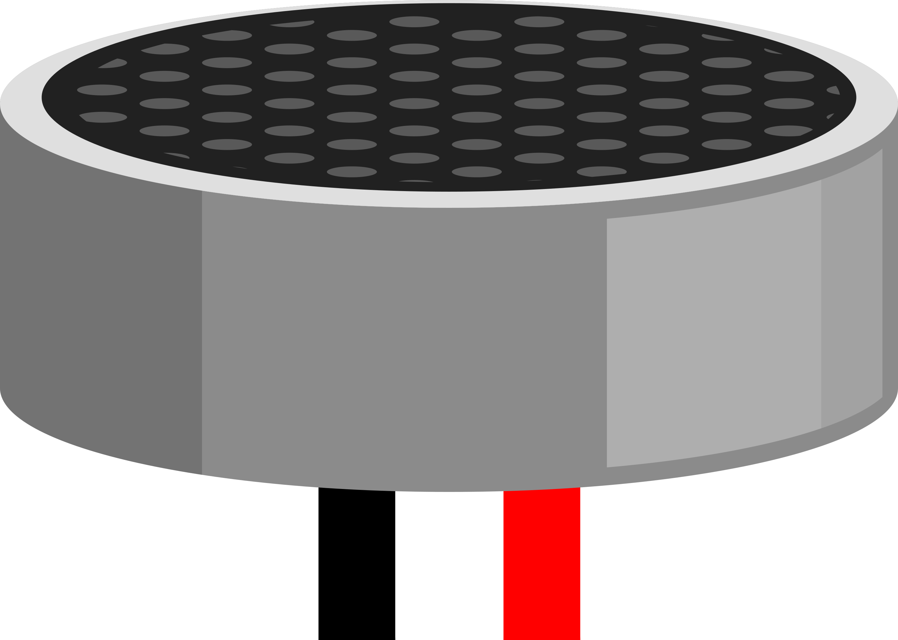
A condenser microphone, also known as a capacitor microphone, is a transducer that converts sound waves into electrical signals through changes in capacitance. It is characterized by a lightweight diaphragm suspended very close to a solid metal plate. When sound waves strike the diaphragm, it moves, causing the capacitance to change, which is then converted into an electrical signal. Condenser microphones are known for their excellent audio quality and sensitivity, making them a popular choice in studio recording, live sound reinforcement, and various communication applications.
Explore Projects Built with Condenser Microphone
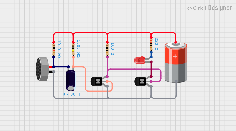
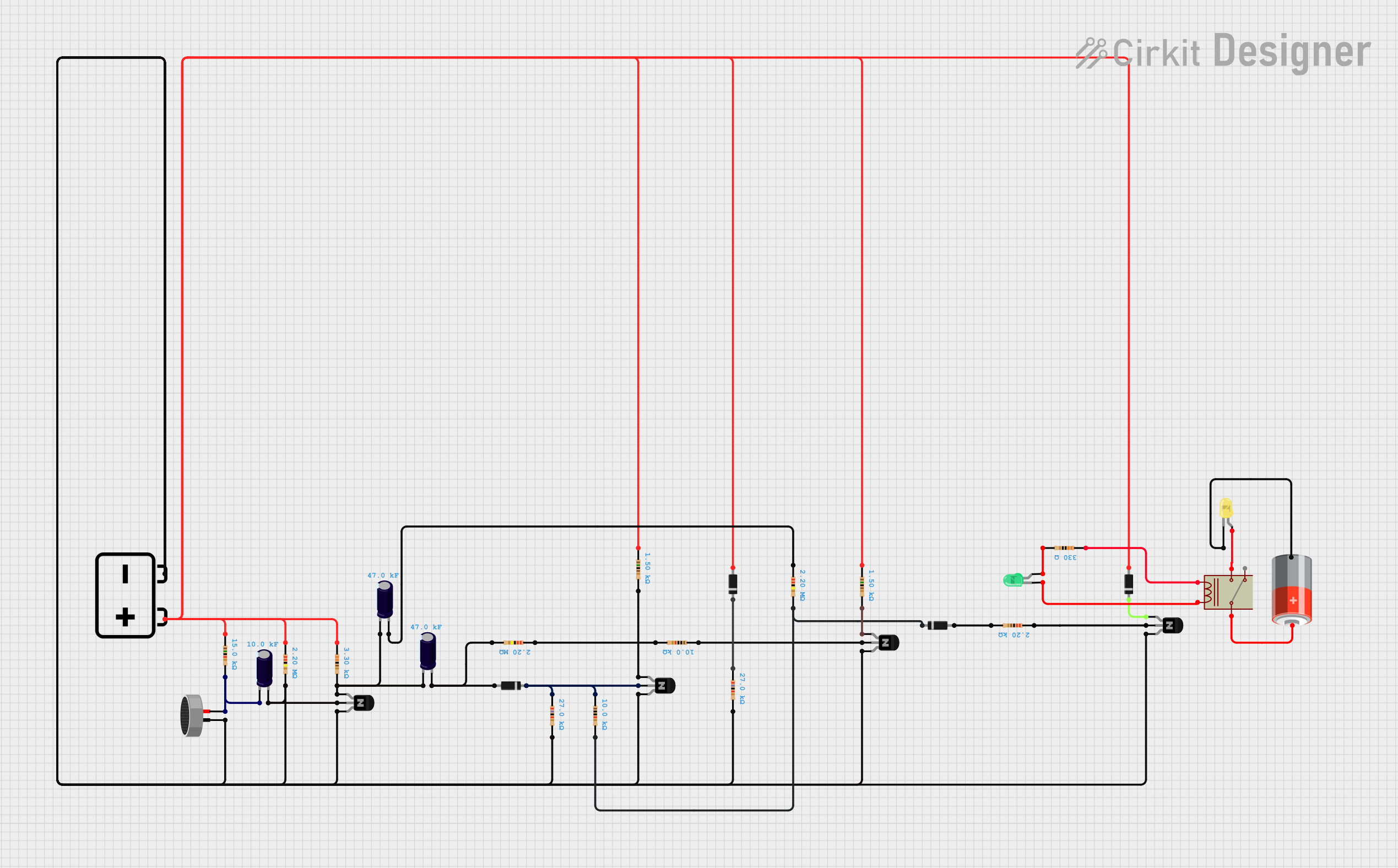
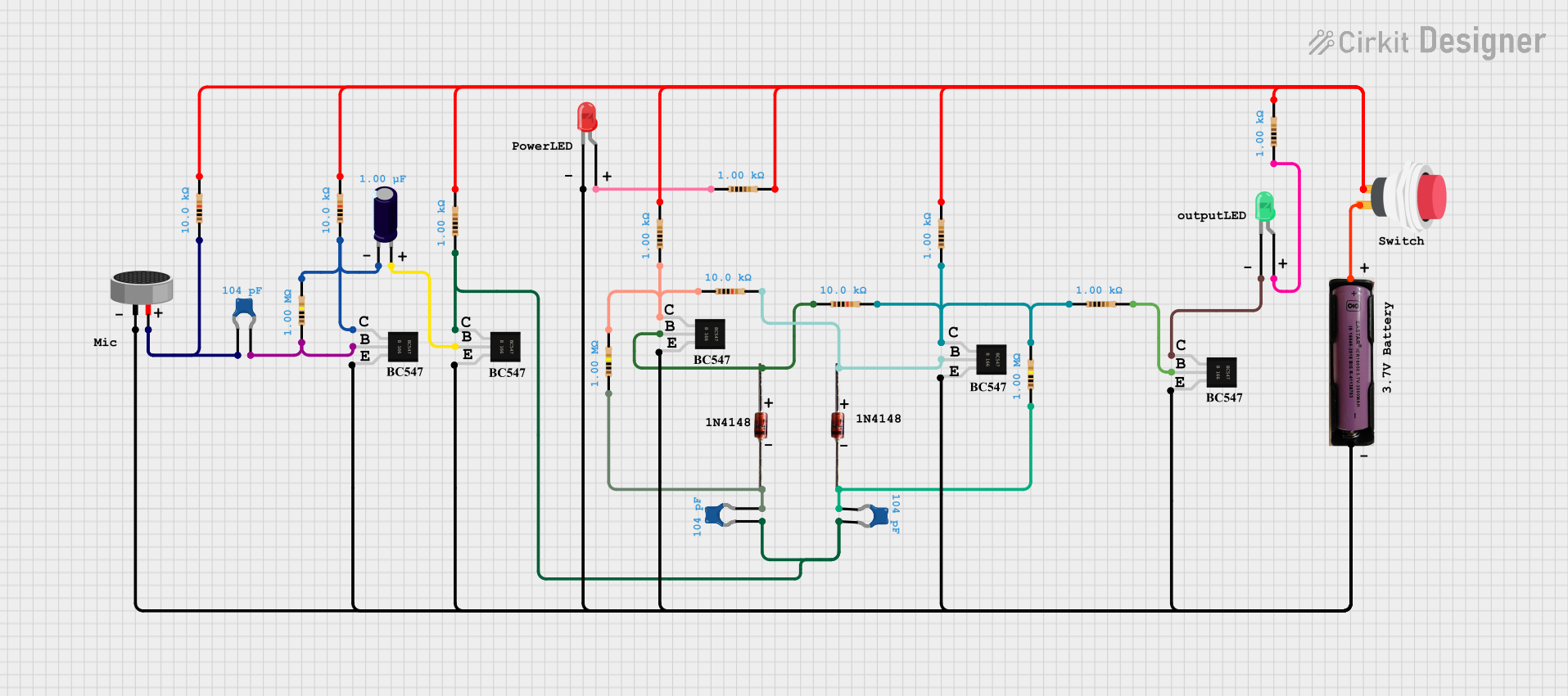
Explore Projects Built with Condenser Microphone
Technical Specifications
Key Technical Details
- Type: Electret Condenser Microphone
- Polar Pattern: Omnidirectional
- Frequency Response: Typically 20 Hz to 20 kHz
- Sensitivity: -45 dB ± 3dB (0dB=1V/Pa at 1kHz)
- Output Impedance: 200 Ohms ± 30% (at 1kHz)
- Operating Voltage: 2V to 10V (standard 3V)
- Signal-to-Noise Ratio: > 60 dB
- Maximum Sound Pressure Level (SPL): 110 dB SPL
Pin Configuration and Descriptions
| Pin Number | Description | Notes |
|---|---|---|
| 1 | Audio Output | Connect to pre-amplifier circuit |
| 2 | Ground | Connect to system ground |
| 3 | Power Supply (Vcc) | Connect to positive voltage |
Usage Instructions
Integration with a Circuit
To use a condenser microphone in a circuit, follow these steps:
- Power Supply: Connect the Vcc pin to a power source between 2V and 10V. For most applications, a 3V power supply is sufficient.
- Grounding: Connect the ground pin to the common ground of the circuit.
- Audio Output: Connect the audio output pin to a pre-amplifier circuit. The pre-amplifier boosts the microphone's signal to a level that can be further processed or recorded.
Best Practices
- Use a shielded cable for the audio output to minimize noise and interference.
- Place the microphone away from sources of electromagnetic interference.
- Implement a pop filter if the microphone is used for vocal recording to reduce plosive sounds.
- For optimal performance, use a power supply with a stable voltage and low ripple.
Example Code for Arduino UNO
Below is an example code snippet for reading an analog signal from a condenser microphone using an Arduino UNO:
// Define the microphone pin
const int micPin = A0; // Analog input pin that the microphone is attached to

void setup() {
  // Initialize serial communication at 9600 bits per second:
  Serial.begin(9600);
}

void loop() {
  // Read the input on analog pin 0:
  int micValue = analogRead(micPin);
  // Print out the value you read:
  Serial.println(micValue);
  delay(1); // Delay in between reads for stability
}
This code will output the raw microphone voltage readings to the serial monitor. To convert these readings into meaningful sound data, further signal processing is required.
Troubleshooting and FAQs
Common Issues
- Low Signal Output: Ensure that the microphone is properly powered and that the pre-amplifier circuit is functioning correctly.
- High Noise Levels: Check for loose connections and ensure that the audio output cable is shielded.
- No Signal: Verify that the microphone is correctly connected to the power supply and pre-amplifier, and that the Arduino is correctly reading the analog input.
Solutions and Tips
- If experiencing low signal output, adjust the gain on the pre-amplifier or check the microphone's placement relative to the sound source.
- For high noise levels, re-route audio cables away from power supplies and other sources of interference.
- In case of no signal, double-check the microphone's pin connections and test the microphone with a multimeter to ensure it is not defective.
FAQs
Q: Can I connect a condenser microphone directly to an Arduino without a pre-amplifier?
A: It is not recommended to connect a condenser microphone directly to an Arduino without a pre-amplifier, as the signal level is too low for the Arduino's ADC to process effectively.
Q: What is the purpose of the power supply for a condenser microphone?
A: The power supply is required to establish the electric field between the diaphragm and the backplate, which is necessary for the microphone to function.
Q: How can I improve the sound quality captured by the condenser microphone?
A: To improve sound quality, use a high-quality pre-amplifier, position the microphone correctly, and minimize background noise and interference during recording.