How to Use I2C Module: Examples, Pinouts, and Specs
Introduction
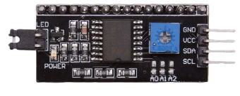
The I2C (Inter-Integrated Circuit) module is a serial communication interface that uses two bidirectional lines, SCL (Serial Clock) and SDA (Serial Data), for data transfer. It is widely used in embedded systems to connect microcontrollers to various peripherals like sensors, EEPROMs, RTCs (Real-Time Clocks), and other I2C-enabled devices. The I2C protocol supports multiple masters and slaves on the same bus, making it ideal for complex communication tasks within a system.
Explore Projects Built with I2C Module
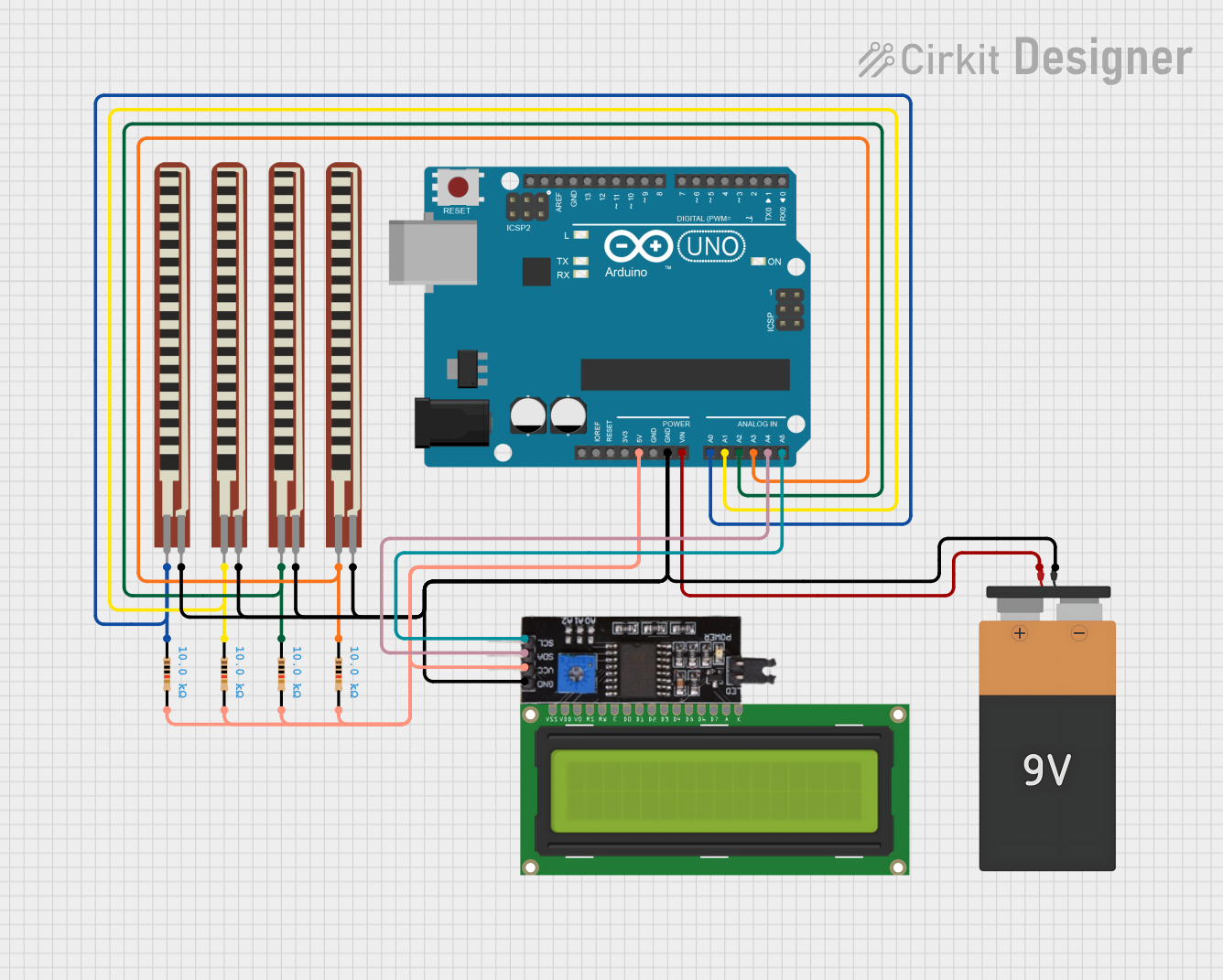
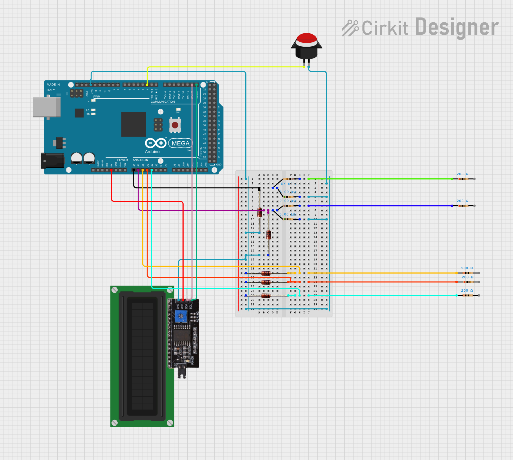
Explore Projects Built with I2C Module
Common Applications and Use Cases
- Sensor data reading (temperature, pressure, humidity, etc.)
- Real-time clock updates
- EEPROM read/write operations
- Display control (e.g., OLED or LCD screens)
- Multi-device coordination in embedded systems
Technical Specifications
Key Technical Details
- Voltage Levels: Typically 3.3V or 5V (logic level depends on the specific module)
- Current Ratings: Varies with the module and connected devices
- Maximum Clock Frequency: Standard mode: 100 kHz, Fast mode: 400 kHz, Fast mode Plus: 1 MHz, High-speed mode: 3.4 MHz
- Maximum Devices on Bus: Up to 112 devices (7-bit addressing mode)
Pin Configuration and Descriptions
| Pin Number | Pin Name | Description |
|---|---|---|
| 1 | VCC | Power supply (3.3V or 5V) |
| 2 | GND | Ground |
| 3 | SCL | Serial Clock Line |
| 4 | SDA | Serial Data Line |
| 5 | ADDR | Address selection pin (if applicable) |
| 6 | INT | Interrupt output (if applicable) |
Usage Instructions
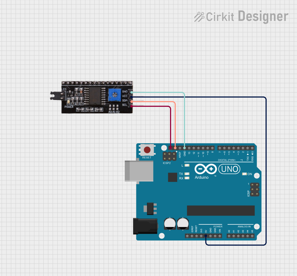
How to Use the Component in a Circuit
- Power Connections: Connect the VCC pin to the power supply and the GND pin to the ground.
- Data Connections: Connect the SCL and SDA pins to the corresponding SCL and SDA pins on the microcontroller.
- Address Configuration: If the module has an ADDR pin, configure it according to the device's datasheet to set the I2C address.
- Pull-up Resistors: Connect pull-up resistors to both SCL and SDA lines. The typical value is 4.7kΩ for 5V systems or 10kΩ for 3.3V systems.
Important Considerations and Best Practices
- Ensure that the logic level of the I2C module matches that of the microcontroller to prevent damage.
- Use appropriate pull-up resistors on the SCL and SDA lines to maintain signal integrity.
- Avoid long I2C bus lines to minimize capacitance and ensure reliable communication.
- Check for address conflicts if multiple I2C devices are on the same bus.
Example Code for Arduino UNO
#include <Wire.h>

void setup() {
  Wire.begin(); // Join the I2C bus as a master or a slave (if an address is specified)

  Serial.begin(9600); // Start serial communication for debugging
}

void loop() {
  Wire.beginTransmission(0x68); // Begin transmission to a device with address 0x68
  // Send data bytes using Wire.write()
  Wire.write(0x00); // For example, write to register 0
  Wire.endTransmission(); // End transmission and release the I2C bus

  delay(1000); // Wait for a second

  Wire.requestFrom(0x68, 1); // Request 1 byte from the device at address 0x68
  while (Wire.available()) { // Check for received data from the slave
    char c = Wire.read(); // Receive a byte
    Serial.println(c); // Print the received byte to the serial monitor
  }

  delay(1000); // Wait for a second
}
Troubleshooting and FAQs
Common Issues Users Might Face
- No Communication: Check connections, ensure correct pull-up resistors are used, and verify that the I2C address is correct.
- Data Corruption: Ensure there are no loose connections and that the bus is not too long or too noisy.
- Device Not Recognized: Confirm that the device is powered and that the I2C address is set correctly.
Solutions and Tips for Troubleshooting
- Use an oscilloscope or logic analyzer to check the integrity of the SCL and SDA signals.
- Use the
Wirelibrary'sonReceive()andonRequest()functions to handle I2C communication more effectively. - Implement error handling in your code to detect and respond to communication failures.
FAQs
Q: Can I connect multiple devices to the same I2C bus? A: Yes, as long as each device has a unique address and the bus capacitance does not exceed the maximum specified by the standard.
Q: What should I do if two devices have the same I2C address? A: Some devices allow you to change their address using jumpers or additional pins. If that's not possible, you may need to use an I2C multiplexer.
Q: How long can the I2C bus be? A: The maximum length of the I2C bus depends on the bus capacitance and the speed of communication. For standard mode, keep the total bus capacitance under 400 pF.
Q: Can I use I2C with devices that have different voltage levels? A: You will need a level shifter to safely connect devices with different logic levels on the same I2C bus.