
How to Use IR : Examples, Pinouts, and Specs
 Design with IR in Cirkit Designer
Introduction
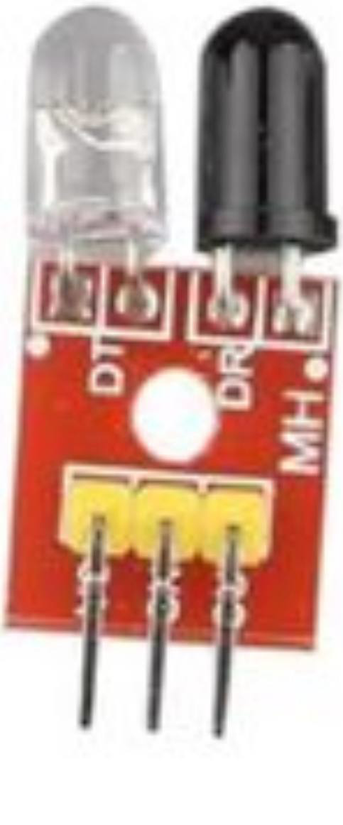
The IR Obstacle Sensor Module is a compact and versatile sensor designed to detect obstacles using infrared (IR) light. It emits IR light and measures the reflection to determine the presence and distance of nearby objects. This module is widely used in robotics, automation systems, and proximity detection applications due to its simplicity and reliability.
Explore Projects Built with IR
 Open Project in Cirkit Designer
 Open Project in Cirkit Designer
 Open Project in Cirkit Designer
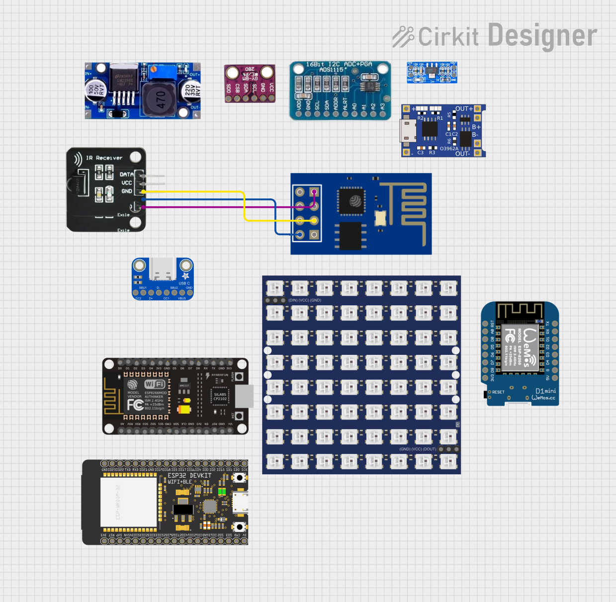 Open Project in Cirkit Designer
Explore Projects Built with IR
Open Project in Cirkit DesignerOpen Project in Cirkit DesignerOpen Project in Cirkit DesignerOpen Project in Cirkit DesignerCommon Applications
- Obstacle detection in robotics
- Line-following robots
- Proximity sensing in automation systems
- Object counters and security systems
- Smart home devices
Technical Specifications
Below are the key technical details of the IR Obstacle Sensor Module:
| Parameter | Value |
|---|---|
| Operating Voltage | 3.3V to 5V |
| Operating Current | 20mA (typical) |
| Detection Range | 2cm to 30cm (adjustable) |
| Output Type | Digital (High/Low) |
| IR Wavelength | 940nm |
| Dimensions | ~3.1cm x 1.5cm x 0.7cm |
| Adjustable Sensitivity | Yes (via onboard potentiometer) |
Pin Configuration
The IR Obstacle Sensor Module typically has three pins:
| Pin | Name | Description |
|---|---|---|
| 1 | VCC | Power supply input (3.3V to 5V) |
| 2 | GND | Ground connection |
| 3 | OUT | Digital output pin (High when no obstacle, Low when an obstacle is detected) |
Usage Instructions
How to Use the IR Obstacle Sensor Module in a Circuit
- Power the Module: Connect the
VCCpin to a 3.3V or 5V power source and theGNDpin to the ground of your circuit. - Connect the Output: Connect the
OUTpin to a digital input pin of your microcontroller or directly to an external circuit. - Adjust Sensitivity: Use the onboard potentiometer to adjust the detection range. Turning the potentiometer clockwise increases the sensitivity, while turning it counterclockwise decreases it.
- Test the Module: Place an object within the detection range and observe the
OUTpin. The onboard LED will also light up when an obstacle is detected.
Important Considerations and Best Practices
- Ambient Light: Avoid using the module in environments with strong ambient IR light (e.g., direct sunlight), as it may interfere with detection.
- Distance Calibration: Adjust the potentiometer carefully to calibrate the detection range for your specific application.
- Power Supply: Ensure a stable power supply to avoid erratic behavior.
- Mounting: Position the sensor so that the IR emitter and receiver are unobstructed for accurate detection.
Example: Connecting to an Arduino UNO
Below is an example of how to connect and use the IR Obstacle Sensor Module with an Arduino UNO:
Circuit Connections
- Connect the
VCCpin of the sensor to the 5V pin on the Arduino. - Connect the
GNDpin of the sensor to the GND pin on the Arduino. - Connect the
OUTpin of the sensor to digital pin 2 on the Arduino.
Arduino Code
// IR Obstacle Sensor Module Example Code
// This code reads the sensor's output and prints the status to the Serial Monitor.

const int sensorPin = 2; // Digital pin connected to the sensor's OUT pin
const int ledPin = 13;   // Onboard LED pin for visual feedback

void setup() {
  pinMode(sensorPin, INPUT); // Set sensor pin as input
  pinMode(ledPin, OUTPUT);   // Set LED pin as output
  Serial.begin(9600);        // Initialize serial communication
}

void loop() {
  int sensorValue = digitalRead(sensorPin); // Read the sensor's output

  if (sensorValue == LOW) {
    // Obstacle detected
    digitalWrite(ledPin, HIGH); // Turn on the LED
    Serial.println("Obstacle detected!");
  } else {
    // No obstacle
    digitalWrite(ledPin, LOW);  // Turn off the LED
    Serial.println("No obstacle.");
  }

  delay(100); // Small delay for stability
}
Troubleshooting and FAQs
Common Issues and Solutions
The sensor is not detecting obstacles:
- Ensure the module is powered correctly (check
VCCandGNDconnections). - Adjust the potentiometer to increase sensitivity.
- Verify that the object is within the detection range (2cm to 30cm).
- Ensure the module is powered correctly (check
False detections or erratic behavior:
- Check for strong ambient IR light sources and reposition the sensor if necessary.
- Ensure a stable power supply to the module.
- Verify that the sensor is not obstructed by dirt or debris.
The onboard LED does not light up:
- Confirm that the module is receiving power.
- Check the potentiometer setting and adjust if needed.
- Test the module with a known working microcontroller or circuit.
FAQs
Q: Can the detection range be extended beyond 30cm?
A: No, the detection range is limited to approximately 30cm. For longer ranges, consider using other sensors like ultrasonic modules.
Q: Can this module detect transparent objects?
A: The module may struggle to detect transparent or highly reflective objects due to the nature of IR reflection.
Q: Is the module compatible with 3.3V systems?
A: Yes, the module works with both 3.3V and 5V systems, making it compatible with a wide range of microcontrollers.
Q: Can multiple sensors be used together?
A: Yes, but ensure proper spacing between sensors to avoid interference from overlapping IR signals.
By following this documentation, you can effectively integrate the IR Obstacle Sensor Module into your projects and troubleshoot common issues with ease.