How to Use Arduino Pro Mini: Examples, Pinouts, and Specs
Introduction
The Arduino Pro Mini is a compact microcontroller board based on the ATmega328P microcontroller. It is designed for users who are familiar with the Arduino environment and are looking for a smaller board for space-constrained projects. With its 14 digital input/output pins, 6 analog inputs, and a 16 MHz quartz crystal oscillator, the Pro Mini is a versatile board suitable for various applications, including robotics, wearables, and automation.
Explore Projects Built with Arduino Pro Mini
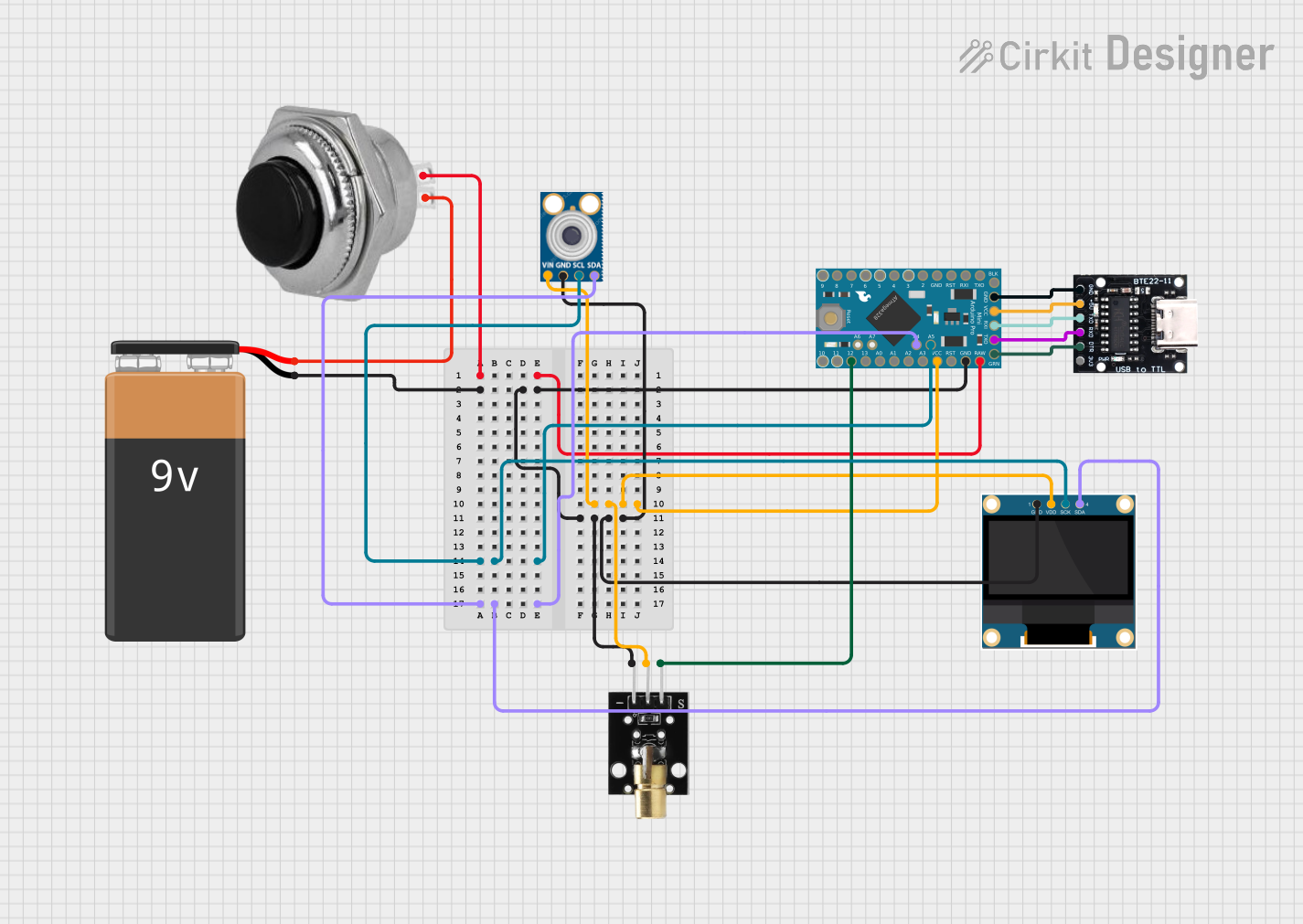
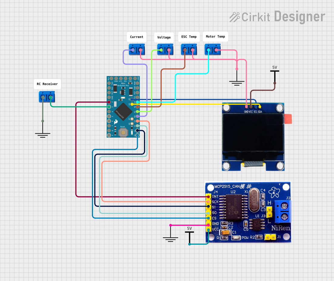
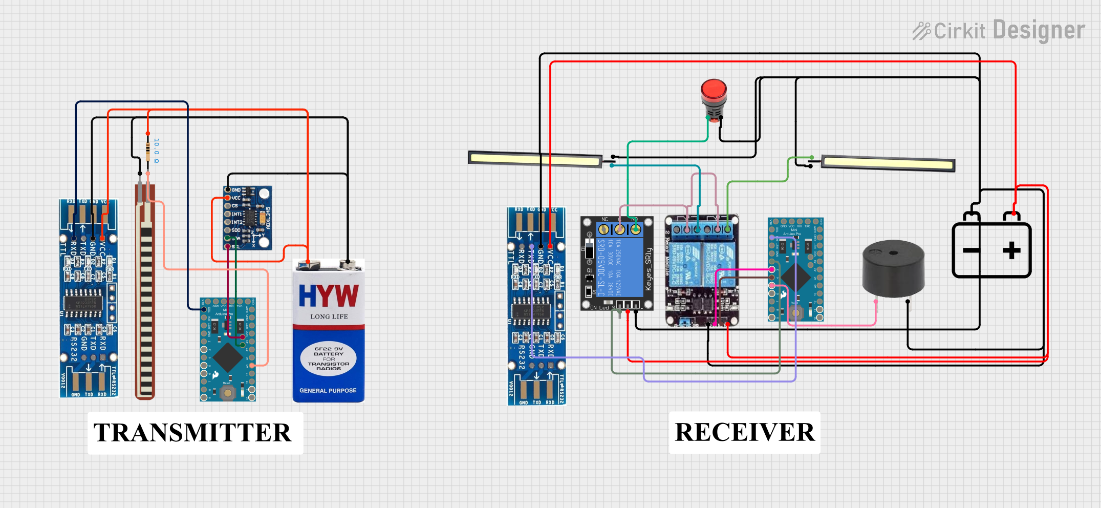
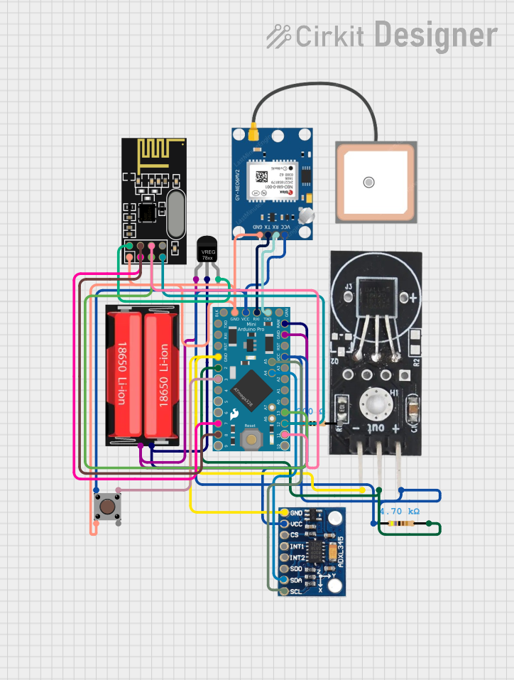
Explore Projects Built with Arduino Pro Mini
Technical Specifications
Key Technical Details
- Microcontroller: ATmega328P
- Operating Voltage: 3.3V or 5V (depending on the model)
- Input Voltage (recommended): 5V - 12V
- Input Voltage (limits): 3.35V - 12V (3.3V model) or 5V - 12V (5V model)
- Digital I/O Pins: 14 (of which 6 provide PWM output)
- Analog Input Pins: 6
- DC Current per I/O Pin: 40 mA
- Flash Memory: 32 KB (ATmega328P) of which 0.5 KB used by bootloader
- SRAM: 2 KB (ATmega328P)
- EEPROM: 1 KB (ATmega328P)
- Clock Speed: 16 MHz
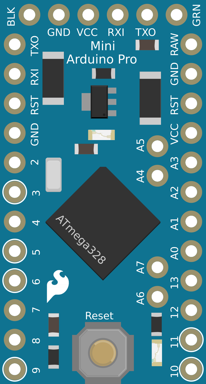
Pin Configuration and Descriptions
| Pin Number | Function | Description |
|---|---|---|
| 1 | RESET | Used to reset the microcontroller |
| 2-3 | PD0/RXD, PD1/TXD | Serial communication pins (RX and TX) |
| 4-9 | PD2-PD7 | Digital pins, PWM available on PD3, PD5, PD6 |
| 10-13 | PB0-PB3 | Digital pins, PWM available on PB1, PB2 |
| 14 | PB4 | Digital pin |
| 15-20 | PC0-PC5 | Analog input pins or digital pins (A0-A5) |
| 21-22 | A6-A7 | Analog input pins (only on some Pro Mini versions) |
| 23-26 | VCC, GND, GND, RAW | Power pins |
| 27-28 | RST, GND | Reset and ground pins |
Usage Instructions
Integrating with a Circuit
To use the Arduino Pro Mini in a circuit, follow these steps:
Powering the Board:
- Connect a power source to the RAW (input voltage) and GND pins if using an unregulated power supply within the recommended voltage limits.
- Alternatively, provide regulated 3.3V or 5V directly to the VCC pin.
Programming the Board:
- The Pro Mini does not come with a USB port. To program it, you'll need an external USB-to-Serial adapter.
- Connect the adapter's TX to the Pro Mini's RX, RX to TX, DTR to RST, VCC to VCC, and GND to GND.
- Select the correct board and port in the Arduino IDE, and upload your sketch.
Connecting I/O:
- Digital pins can be used as input or output pins. Configure them in your sketch using
pinMode(),digitalWrite(), anddigitalRead()functions. - Analog pins can read analog voltages using the
analogRead()function.
- Digital pins can be used as input or output pins. Configure them in your sketch using
Best Practices
- Always disconnect the board from power sources before making or altering connections.
- Use a current limiting resistor with LEDs and other sensitive components.
- Avoid supplying voltage higher than the recommended limits to prevent damage.
- Ensure that the total current drawn from the I/O pins does not exceed the maximum limit.
Example Code for Arduino UNO
Here's a simple example of blinking an LED connected to pin 13 of the Arduino Pro Mini:
// Pin 13 has an LED connected on most Arduino boards.
int ledPin = 13;

// The setup routine runs once when you press reset:
void setup() {
  // Initialize the digital pin as an output.
  pinMode(ledPin, OUTPUT);
}

// The loop routine runs over and over again forever:
void loop() {
  digitalWrite(ledPin, HIGH);   // Turn the LED on (HIGH is the voltage level)
  delay(1000);                  // Wait for a second
  digitalWrite(ledPin, LOW);    // Turn the LED off by making the voltage LOW
  delay(1000);                  // Wait for a second
}
Troubleshooting and FAQs
Common Issues
- Board not recognized: Ensure that the USB-to-Serial adapter drivers are installed and that the adapter is properly connected to the Pro Mini.
- Sketch not uploading: Check the connections between the USB-to-Serial adapter and the Pro Mini. Ensure that the correct board and port are selected in the Arduino IDE.
- Unexpected behavior: Double-check your code for errors. Ensure that the power supply is stable and within the recommended voltage range.
FAQs
Q: Can I power the Arduino Pro Mini with a 9V battery? A: Yes, you can connect a 9V battery to the RAW input if you're using the 5V version of the Pro Mini. For the 3.3V version, ensure the voltage does not exceed the input voltage limits.
Q: How do I connect a sensor to the Pro Mini? A: Connect the sensor's VCC to the Pro Mini's VCC, GND to GND, and the signal pin to one of the Pro Mini's analog or digital I/O pins, depending on the sensor's output.
Q: What is the purpose of the A6 and A7 pins? A: A6 and A7 are additional analog input pins available on some Pro Mini boards. They can only be used as analog inputs and do not have digital I/O capabilities.
For further assistance, consult the Arduino forums and the extensive community resources available online.