How to Use tp4056: Examples, Pinouts, and Specs
Introduction
The TP4056 is a lithium-ion battery charger IC manufactured by Direncnet, with the part ID ESP32. It is specifically designed for charging single-cell lithium-ion batteries using a constant current/constant voltage (CC/CV) charging profile. This component is widely used due to its simplicity, efficiency, and built-in safety features such as thermal regulation and over-voltage protection.
Explore Projects Built with tp4056


Explore Projects Built with tp4056
Common Applications and Use Cases
- Charging single-cell lithium-ion or lithium-polymer batteries
- Portable electronics and power banks
- DIY electronics projects
- Battery-powered IoT devices
- Integration with microcontroller-based systems (e.g., Arduino, ESP32)
Technical Specifications
The TP4056 is a versatile and reliable charging IC. Below are its key technical specifications:
| Parameter | Value |
|---|---|
| Input Voltage Range | 4.0V to 8.0V |
| Charging Voltage | 4.2V ± 1% |
| Maximum Charging Current | 1A (adjustable via external resistor) |
| Charging Method | Constant Current / Constant Voltage (CC/CV) |
| Operating Temperature | -40°C to +85°C |
| Standby Current | < 55µA |
| Thermal Regulation | Automatically reduces current to prevent overheating |
| Protection Features | Over-voltage, over-temperature, and reverse polarity protection |
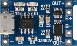
Pin Configuration and Descriptions
The TP4056 IC typically comes in a 6-pin SOP package. Below is the pin configuration:
| Pin Name | Pin Number | Description |
|---|---|---|
| VCC | 1 | Input power supply (4.0V to 8.0V). Connect to a regulated DC source. |
| GND | 2 | Ground pin. Connect to the system ground. |
| BAT | 3 | Battery connection pin. Connect directly to the positive terminal of the battery. |
| PROG | 4 | Charging current programming pin. Connect a resistor to set the charging current. |
| STAT1 | 5 | Status indicator pin 1. Used to indicate charging status (e.g., charging or complete). |
| STAT2 | 6 | Status indicator pin 2. Used to indicate charging errors or other states. |
Usage Instructions
How to Use the TP4056 in a Circuit
- Power Supply: Connect a regulated DC power source (4.0V to 8.0V) to the VCC pin. Ensure the power source can supply sufficient current for the charging process.
- Battery Connection: Connect the positive terminal of the lithium-ion battery to the BAT pin and the negative terminal to GND.
- Set Charging Current: Use a resistor (RPROG) connected to the PROG pin to set the desired charging current. The charging current can be calculated using the formula: [ I_{CHARGE} = \frac{1200}{R_{PROG}} ] For example, using a 1.2kΩ resistor will set the charging current to 1A.
- Status Indicators: Connect LEDs to the STAT1 and STAT2 pins (with appropriate current-limiting resistors) to monitor the charging status:
- STAT1 ON, STAT2 OFF: Charging in progress.
- STAT1 OFF, STAT2 ON: Charging complete.
- Both OFF: No battery connected or standby mode.
Important Considerations and Best Practices
- Thermal Management: Ensure proper heat dissipation by using a PCB with adequate thermal pads or heat sinks.
- Input Voltage: Avoid exceeding the maximum input voltage of 8.0V to prevent damage to the IC.
- Battery Protection: Use a battery with built-in protection circuitry to prevent overcharging or deep discharge.
- Capacitors: Place a 1µF ceramic capacitor close to the VCC pin and a 10µF capacitor near the BAT pin for stable operation.
Example: Using TP4056 with Arduino UNO
The TP4056 can be used to charge a battery that powers an Arduino UNO. Below is an example of monitoring the charging status using the Arduino:
// TP4056 Status Monitoring with Arduino UNO
// Connect STAT1 to Arduino pin 2 and STAT2 to pin 3

const int stat1Pin = 2; // STAT1 pin connected to Arduino digital pin 2
const int stat2Pin = 3; // STAT2 pin connected to Arduino digital pin 3

void setup() {
  pinMode(stat1Pin, INPUT); // Set STAT1 as input
  pinMode(stat2Pin, INPUT); // Set STAT2 as input
  Serial.begin(9600);       // Initialize serial communication
}

void loop() {
  int stat1 = digitalRead(stat1Pin); // Read STAT1 pin state
  int stat2 = digitalRead(stat2Pin); // Read STAT2 pin state

  if (stat1 == HIGH && stat2 == LOW) {
    Serial.println("Charging in progress...");
  } else if (stat1 == LOW && stat2 == HIGH) {
    Serial.println("Charging complete.");
  } else {
    Serial.println("No battery or standby mode.");
  }

  delay(1000); // Wait for 1 second before checking again
}
Troubleshooting and FAQs
Common Issues and Solutions
Battery Not Charging
- Cause: Incorrect input voltage or insufficient current supply.
- Solution: Verify that the input voltage is between 4.0V and 8.0V and the power source can supply enough current.
Overheating
- Cause: High ambient temperature or insufficient heat dissipation.
- Solution: Improve thermal management by adding heat sinks or increasing PCB copper area.
Status LEDs Not Working
- Cause: Incorrect resistor values or faulty connections.
- Solution: Check the LED connections and ensure appropriate current-limiting resistors are used.
Charging Current Too Low
- Cause: Incorrect RPROG resistor value.
- Solution: Recalculate and replace the RPROG resistor to achieve the desired charging current.
FAQs
Q1: Can the TP4056 charge multiple batteries in series?
A1: No, the TP4056 is designed for single-cell lithium-ion batteries only. Charging multiple cells in series requires a specialized multi-cell charger.
Q2: What happens if the input voltage exceeds 8.0V?
A2: Exceeding the maximum input voltage can damage the IC. Always use a regulated power source within the specified range.
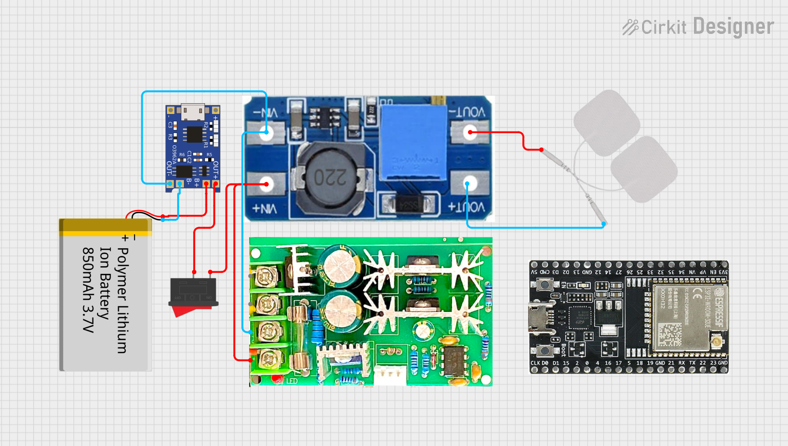
Q3: Can I use the TP4056 to power a device while charging the battery?
A3: Yes, but it is recommended to use a load-sharing circuit to prevent overloading the IC and ensure stable operation.
Q4: How do I adjust the charging voltage?
A4: The charging voltage is fixed at 4.2V and cannot be adjusted. For other voltages, consider using a different charger IC.