How to Use MPX5700AP: Examples, Pinouts, and Specs
Introduction
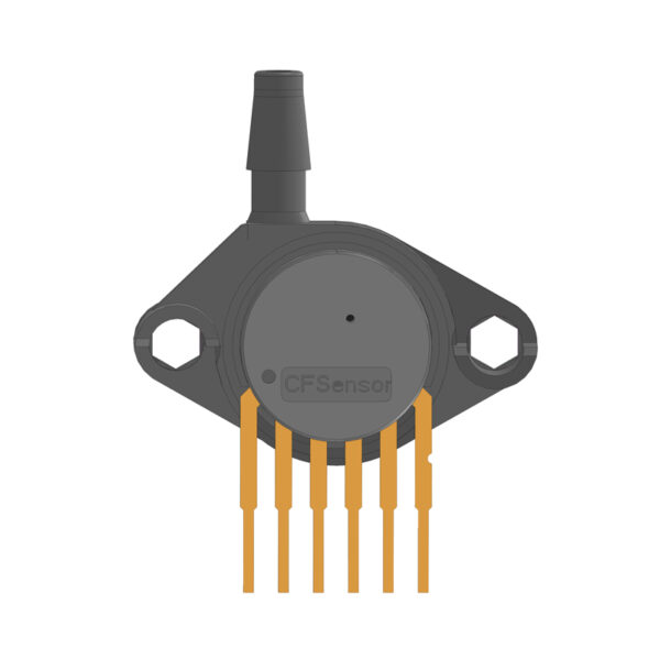
The MPX5700AP is a piezoresistive pressure sensor manufactured by NXP. It provides a linear voltage output that is directly proportional to the applied pressure, making it an ideal choice for applications requiring precise pressure measurements. This sensor is designed to measure pressures in the range of 0 to 700 kPa and is commonly used in automotive systems (e.g., engine control), industrial equipment, and medical devices.
Explore Projects Built with MPX5700AP

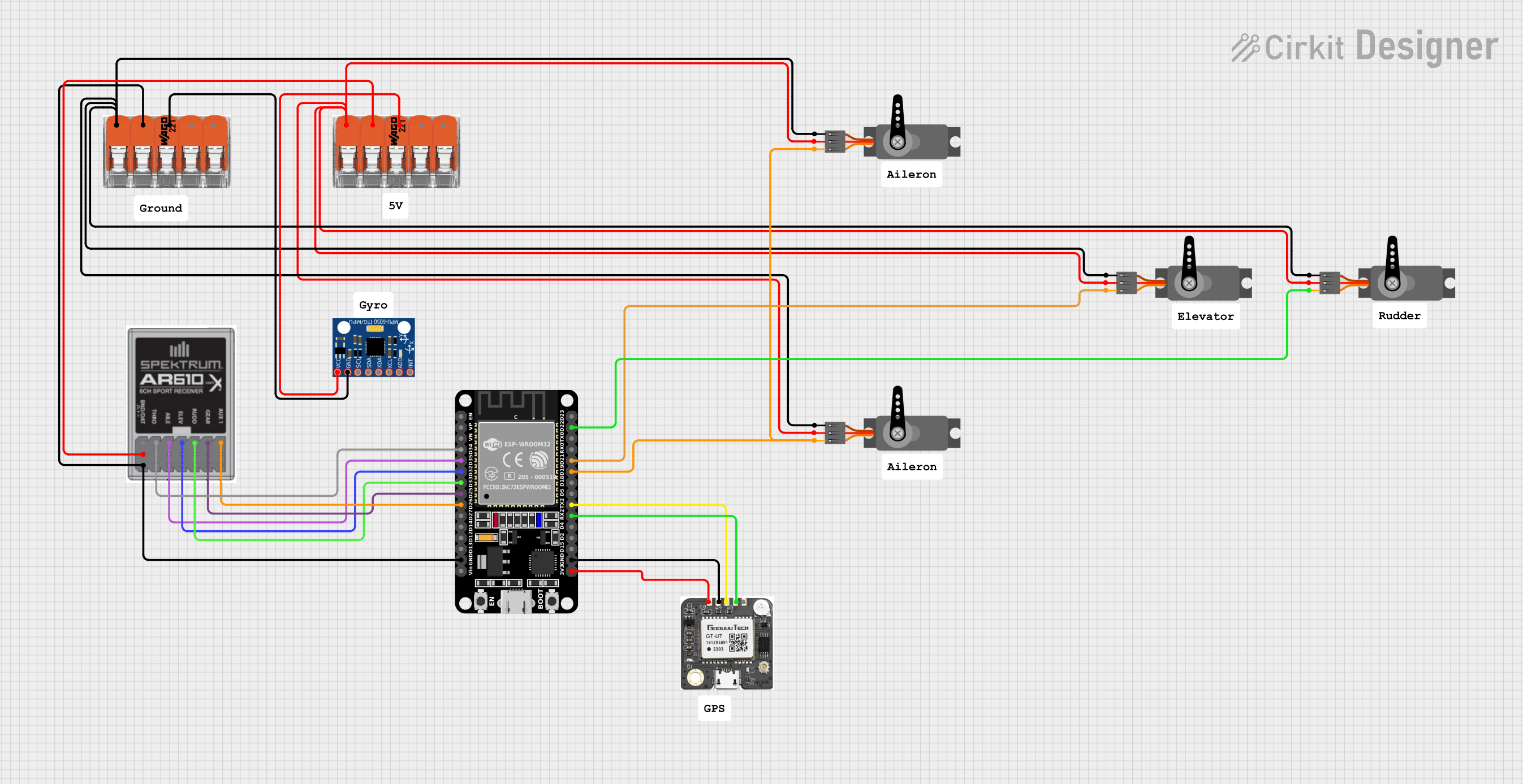

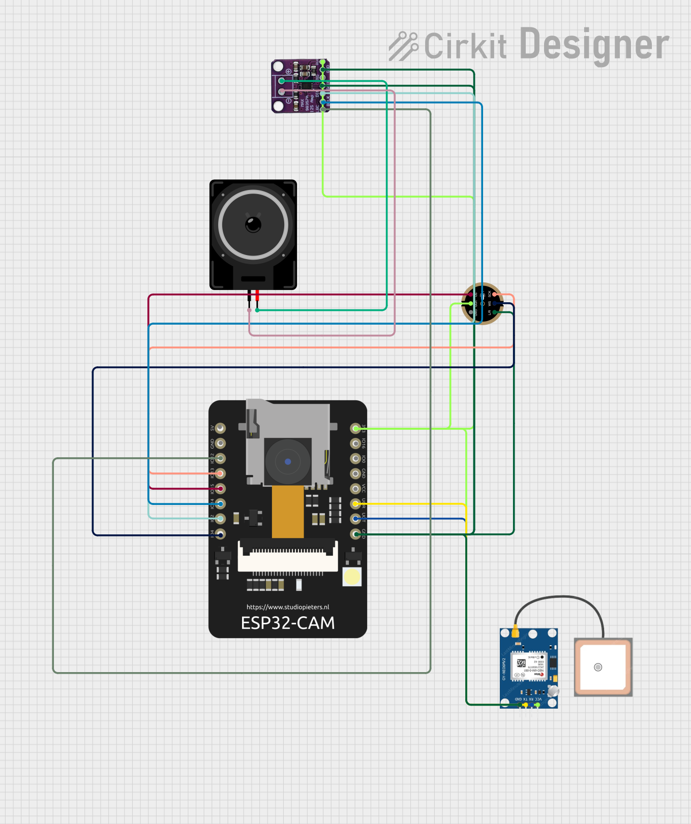
Explore Projects Built with MPX5700AP
Common Applications:
- Automotive: Engine control, fuel pressure monitoring, and transmission systems.
- Industrial: Pneumatic systems, HVAC systems, and process control.
- Medical: Respiratory devices and blood pressure monitoring.
Technical Specifications
The MPX5700AP is a highly reliable and accurate pressure sensor. Below are its key technical details:
Key Specifications:
| Parameter | Value |
|---|---|
| Pressure Range | 0 to 700 kPa |
| Supply Voltage (Vcc) | 4.75 V to 5.25 V |
| Output Voltage Range | 0.2 V to 4.7 V |
| Sensitivity | 6.4 mV/kPa |
| Accuracy | ±1.5% of full-scale span |
| Operating Temperature | -40°C to +125°C |
| Response Time | 1 ms |
| Media Compatibility | Dry air and non-corrosive gases |
Pin Configuration and Descriptions:
The MPX5700AP has a 6-pin configuration. The table below describes each pin:
| Pin Number | Pin Name | Description |
|---|---|---|
| 1 | Vout | Analog output voltage proportional to pressure |
| 2 | GND | Ground |
| 3 | Vcc | Supply voltage (4.75 V to 5.25 V) |
| 4 | NC | Not connected |
| 5 | NC | Not connected |
| 6 | NC | Not connected |
Note: Pins 4, 5, and 6 are not internally connected and can be left unconnected in the circuit.
Usage Instructions
How to Use the MPX5700AP in a Circuit:
- Power Supply: Connect the Vcc pin (Pin 3) to a regulated 5V power supply and the GND pin (Pin 2) to the ground of the circuit.
- Output Signal: The Vout pin (Pin 1) provides an analog voltage output proportional to the applied pressure. This output can be read using an ADC (Analog-to-Digital Converter) on a microcontroller.
- Pressure Measurement: The sensor measures the pressure applied to its port and outputs a voltage in the range of 0.2 V to 4.7 V, corresponding to 0 to 700 kPa.
Important Considerations:
- Media Compatibility: Ensure the sensor is exposed only to dry air or non-corrosive gases to avoid damage.
- Power Supply Stability: Use a stable 5V power supply to ensure accurate readings.
- Calibration: For precise applications, calibrate the sensor to account for any offset or gain errors.
- Mounting: Avoid mechanical stress on the sensor during installation to prevent damage or inaccurate readings.
Example: Connecting MPX5700AP to an Arduino UNO
Below is an example of how to connect the MPX5700AP to an Arduino UNO and read the pressure values:
Circuit Connections:
- Connect Pin 3 (Vcc) to the Arduino's 5V pin.
- Connect Pin 2 (GND) to the Arduino's GND pin.
- Connect Pin 1 (Vout) to an analog input pin on the Arduino (e.g., A0).
Arduino Code:
// Define the analog input pin connected to the MPX5700AP
const int pressurePin = A0;

// Define the sensor's output voltage range and pressure range
const float Vout_min = 0.2; // Minimum output voltage (V)
const float Vout_max = 4.7; // Maximum output voltage (V)
const float P_min = 0.0;    // Minimum pressure (kPa)
const float P_max = 700.0;  // Maximum pressure (kPa)

void setup() {
  Serial.begin(9600); // Initialize serial communication
}

void loop() {
  // Read the analog value from the sensor
  int sensorValue = analogRead(pressurePin);

  // Convert the analog value to voltage
  float voltage = sensorValue * (5.0 / 1023.0);

  // Calculate the pressure based on the sensor's transfer function
  float pressure = ((voltage - Vout_min) * (P_max - P_min) /
                    (Vout_max - Vout_min)) + P_min;

  // Print the pressure value to the Serial Monitor
  Serial.print("Pressure: ");
  Serial.print(pressure);
  Serial.println(" kPa");

  delay(500); // Wait for 500 ms before the next reading
}
Note: Ensure the Arduino's ADC reference voltage is set to 5V for accurate readings.
Troubleshooting and FAQs
Common Issues and Solutions:
No Output Voltage:
- Cause: Incorrect wiring or insufficient power supply.
- Solution: Verify all connections and ensure the power supply is within the specified range (4.75 V to 5.25 V).
Inaccurate Readings:
- Cause: Electrical noise or unstable power supply.
- Solution: Use decoupling capacitors (e.g., 0.1 µF) near the Vcc pin to filter noise.
Sensor Damage:
- Cause: Exposure to incompatible media or excessive pressure.
- Solution: Ensure the sensor is used only with dry air or non-corrosive gases and within the specified pressure range.
Output Voltage Stuck at Minimum or Maximum:
- Cause: Sensor malfunction or incorrect calibration.
- Solution: Check the sensor's connections and recalibrate if necessary.
FAQs:
Q1: Can the MPX5700AP measure negative pressure?
A1: No, the MPX5700AP is designed to measure pressures in the range of 0 to 700 kPa only.
Q2: What is the response time of the sensor?
A2: The sensor has a response time of 1 ms, making it suitable for real-time applications.
Q3: Can I use the MPX5700AP with a 3.3V microcontroller?
A3: No, the MPX5700AP requires a 5V power supply for proper operation. Use a level shifter if interfacing with a 3.3V microcontroller.
Q4: How do I protect the sensor from overpressure?
A4: Use a pressure relief valve or a mechanical stopper to prevent the applied pressure from exceeding 700 kPa.
By following this documentation, users can effectively integrate the MPX5700AP into their projects and achieve accurate pressure measurements.