Cirkit Designer Logo
Cirkit Designer
Your all-in-one circuit design IDE
Home / 
Component Documentation

How to Use CardKb: Examples, Pinouts, and Specs

Image of CardKb
Cirkit Designer LogoDesign with CardKb in Cirkit Designer

Introduction

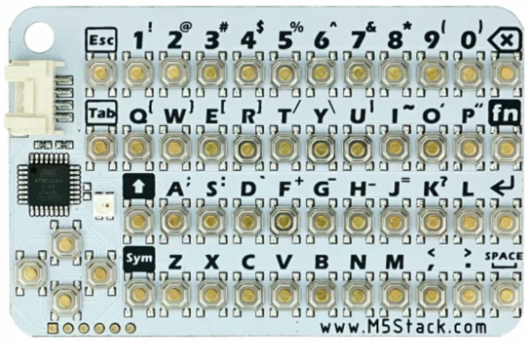
The CardKb is a compact and versatile keyboard module designed for efficient data entry. Manufactured by m5Stack with the part ID MEGA8A, this device is ideal for applications requiring a small, reliable input interface. Its layout is optimized for quick access to frequently used functions, making it a popular choice for point-of-sale systems, kiosks, and embedded systems. The CardKb is compatible with microcontrollers like Arduino and ESP32, offering seamless integration into various projects.

Explore Projects Built with CardKb

Use Cirkit Designer to design, explore, and prototype these projects online. Some projects support real-time simulation. Click "Open Project" to start designing instantly!
Arduino UNO-Based Card Counter with IR Sensor and LCD Display
Image of card counter: A project utilizing CardKb in a practical application
This circuit is a card counting system that uses an Arduino UNO to control two motors via an L298N motor driver, an IR sensor to detect cards, and an I2C LCD to display the count. The system includes pushbuttons for power, start/stop, and reset functions, and is powered by a 12V battery.
Cirkit Designer LogoOpen Project in Cirkit Designer
Arduino UNO Based NFC Reader with Membrane Keypad Interface
Image of NFC_serial: A project utilizing CardKb in a practical application
This circuit features an Arduino UNO connected to a 4x4 membrane matrix keypad, an NFC/RFID reader, and powered by a 9V battery. The Arduino is programmed to detect and display keypad inputs and read NFC tags, likely for an access control or identification system. The NFC/RFID reader communicates with the Arduino via I2C (using SDA and SCL lines), and the keypad is interfaced using digital IO pins.
Cirkit Designer LogoOpen Project in Cirkit Designer
Arduino UNO Keypad-Controlled LED and Buzzer System with RTC and Bluetooth
Image of Uni: A project utilizing CardKb in a practical application
This circuit is an Arduino-based keypad interface system that reads input from a 4x4 membrane matrix keypad and displays the pressed key on the serial monitor. It also includes a real-time clock (RTC) module, a Bluetooth module, and visual indicators using red and green LEDs. Additionally, a buzzer is controlled via an NPN transistor for audio feedback.
Cirkit Designer LogoOpen Project in Cirkit Designer
ESP32-Based Smart Access Control System with RFID, Keypad, and OLED Display
Image of Insight Automata Iot device: A project utilizing CardKb in a practical application
This circuit is an ESP32-based system that integrates multiple input devices including a membrane keypad, pushbuttons, an RFID reader, and an SD card module for data logging. It also features an OLED display for visual feedback and a red LED indicator, making it suitable for applications requiring user interaction, data storage, and network connectivity.
Cirkit Designer LogoOpen Project in Cirkit Designer

Explore Projects Built with CardKb

Use Cirkit Designer to design, explore, and prototype these projects online. Some projects support real-time simulation. Click "Open Project" to start designing instantly!
Image of card counter: A project utilizing CardKb in a practical application
Arduino UNO-Based Card Counter with IR Sensor and LCD Display
This circuit is a card counting system that uses an Arduino UNO to control two motors via an L298N motor driver, an IR sensor to detect cards, and an I2C LCD to display the count. The system includes pushbuttons for power, start/stop, and reset functions, and is powered by a 12V battery.
Cirkit Designer LogoOpen Project in Cirkit Designer
Image of NFC_serial: A project utilizing CardKb in a practical application
Arduino UNO Based NFC Reader with Membrane Keypad Interface
This circuit features an Arduino UNO connected to a 4x4 membrane matrix keypad, an NFC/RFID reader, and powered by a 9V battery. The Arduino is programmed to detect and display keypad inputs and read NFC tags, likely for an access control or identification system. The NFC/RFID reader communicates with the Arduino via I2C (using SDA and SCL lines), and the keypad is interfaced using digital IO pins.
Cirkit Designer LogoOpen Project in Cirkit Designer
Image of Uni: A project utilizing CardKb in a practical application
Arduino UNO Keypad-Controlled LED and Buzzer System with RTC and Bluetooth
This circuit is an Arduino-based keypad interface system that reads input from a 4x4 membrane matrix keypad and displays the pressed key on the serial monitor. It also includes a real-time clock (RTC) module, a Bluetooth module, and visual indicators using red and green LEDs. Additionally, a buzzer is controlled via an NPN transistor for audio feedback.
Cirkit Designer LogoOpen Project in Cirkit Designer
Image of Insight Automata Iot device: A project utilizing CardKb in a practical application
ESP32-Based Smart Access Control System with RFID, Keypad, and OLED Display
This circuit is an ESP32-based system that integrates multiple input devices including a membrane keypad, pushbuttons, an RFID reader, and an SD card module for data logging. It also features an OLED display for visual feedback and a red LED indicator, making it suitable for applications requiring user interaction, data storage, and network connectivity.
Cirkit Designer LogoOpen Project in Cirkit Designer

Common Applications

  • Point-of-sale (POS) systems
  • Kiosks and vending machines
  • Embedded systems requiring compact input devices
  • Prototyping and development of user interfaces
  • IoT devices with limited space for input peripherals

Technical Specifications

The following table outlines the key technical details of the CardKb:

Parameter Specification
Manufacturer m5Stack
Part ID MEGA8A
Communication Protocol I2C
Operating Voltage 3.3V
Dimensions 65mm x 24mm x 3.6mm
Key Count 44 keys
I2C Address 0x5F (default)
Compatibility Arduino, ESP32, and other I2C devices

Pin Configuration

The CardKb uses a simple 4-pin interface for communication and power. Below is the pin configuration:

Pin Name Description
1 GND Ground
2 VCC Power supply (3.3V)
3 SDA I2C data line
4 SCL I2C clock line

Usage Instructions

Connecting the CardKb to a Microcontroller

To use the CardKb, connect its pins to the corresponding pins on your microcontroller. For example, when using an Arduino UNO:

  1. Connect the GND pin of the CardKb to the GND pin of the Arduino.
  2. Connect the VCC pin of the CardKb to the 3.3V pin of the Arduino.
  3. Connect the SDA pin of the CardKb to the A4 pin of the Arduino (I2C data line).
  4. Connect the SCL pin of the CardKb to the A5 pin of the Arduino (I2C clock line).

Sample Arduino Code

Below is an example of how to interface the CardKb with an Arduino UNO to read key presses:

#include <Wire.h> // Include the Wire library for I2C communication

#define CARDKB_I2C_ADDRESS 0x5F // Default I2C address for CardKb

void setup() {
  Wire.begin(); // Initialize I2C communication
  Serial.begin(9600); // Start serial communication for debugging
  Serial.println("CardKb Initialized. Press any key...");
}

void loop() {
  Wire.requestFrom(CARDKB_I2C_ADDRESS, 1); // Request 1 byte from CardKb
  if (Wire.available()) {
    char key = Wire.read(); // Read the key pressed
    if (key != 0) { // Check if a key was pressed
      Serial.print("Key Pressed: ");
      Serial.println(key); // Print the key to the Serial Monitor
    }
  }
  delay(100); // Small delay to avoid flooding the Serial Monitor
}

Important Considerations

  • Ensure the CardKb is powered with 3.3V. Supplying 5V may damage the module.
  • The default I2C address is 0x5F. If multiple I2C devices are connected, ensure there are no address conflicts.
  • Use pull-up resistors on the SDA and SCL lines if your microcontroller does not have internal pull-ups enabled.

Troubleshooting and FAQs

Common Issues and Solutions

  1. No response from the CardKb:

    • Verify the wiring connections, especially the SDA and SCL lines.
    • Ensure the CardKb is powered with 3.3V.
    • Check if the I2C address (0x5F) matches the one in your code.
  2. Incorrect or garbled key presses:

    • Ensure the I2C communication speed is set to 100kHz (standard mode).
    • Check for noise or interference on the I2C lines.
  3. Multiple I2C devices not working:

    • Confirm that all devices have unique I2C addresses.
    • Use an I2C scanner sketch to detect connected devices and their addresses.

FAQs

Q: Can the CardKb be used with 5V microcontrollers?
A: Yes, but you must use a level shifter to step down the 5V signals to 3.3V for the CardKb.

Q: How do I change the I2C address of the CardKb?
A: The I2C address is fixed at 0x5F and cannot be changed.

Q: Can I use the CardKb with an ESP32?
A: Yes, the CardKb is fully compatible with the ESP32. Connect the SDA and SCL pins to the appropriate I2C pins on the ESP32.

Q: What is the debounce time for the keys?
A: The CardKb has built-in debouncing, so no additional software debounce is required.

By following this documentation, you can easily integrate the CardKb into your projects for efficient and reliable data entry.