How to Use Arduino Mkr Zero: Examples, Pinouts, and Specs
Introduction
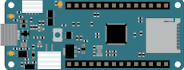
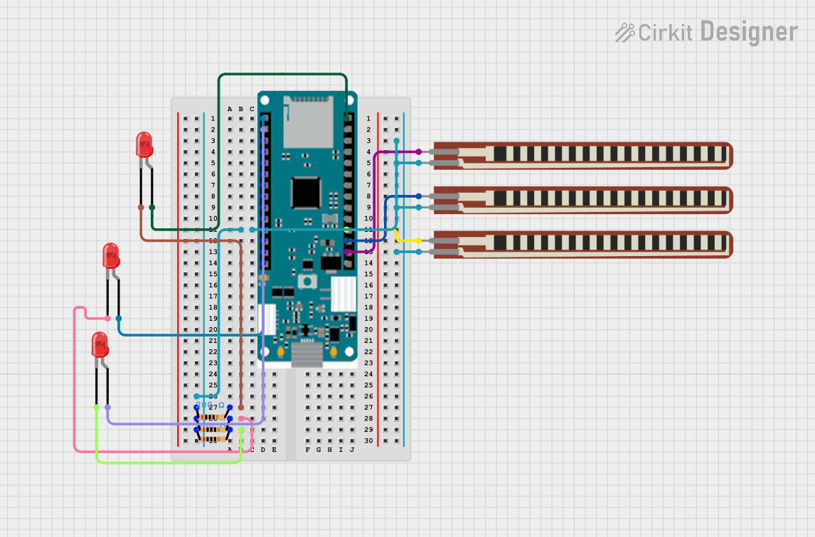
The Arduino MKR Zero is a microcontroller board that blends the capabilities of the Arduino Zero with the added feature of wireless connectivity, including WiFi and Bluetooth. It is designed around the Atmel SAMD21 microcontroller, a 32-bit ARM Cortex-M0+ processor. This board is ideal for projects requiring a compact form factor, low power consumption, and wireless communication capabilities. Common applications include IoT devices, wearable technology, and smart home applications.
Explore Projects Built with Arduino Mkr Zero
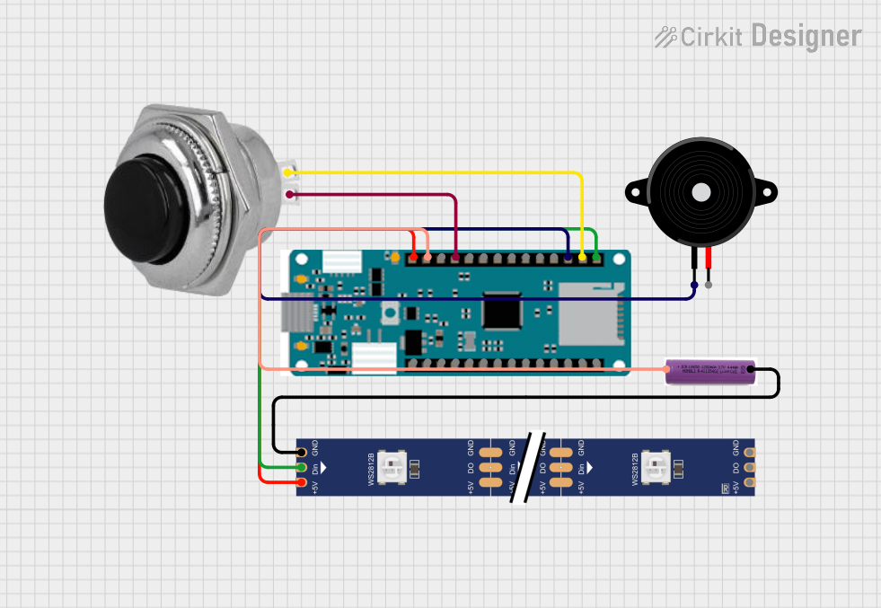
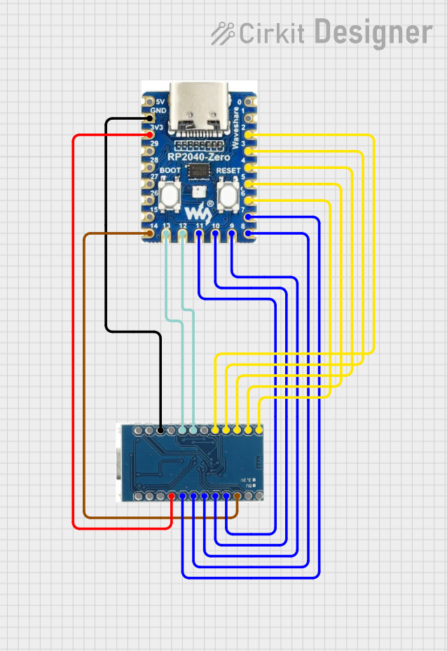
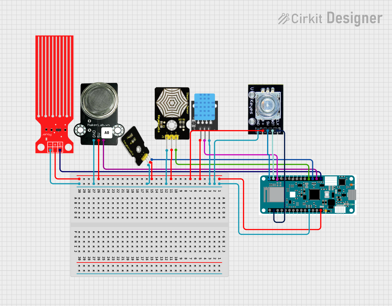
Explore Projects Built with Arduino Mkr Zero
Technical Specifications
Key Technical Details
- Microcontroller: Atmel SAMD21 (32-bit ARM Cortex-M0+)
- Operating Voltage: 3.3V
- Input Voltage (recommended): 5V via USB or Vin pin
- Input Voltage (limit): 6-20V
- Digital I/O Pins: 22
- PWM Pins: 12
- Analog Input Pins: 7 (ADC 8/10/12 bit)
- Analog Output Pins: 1 (DAC 10 bit)
- DC Current per I/O Pin: 7 mA
- Flash Memory: 256 KB
- SRAM: 32 KB
- Clock Speed: 48 MHz
- Connectivity: WiFi and Bluetooth LE
- Interfaces: SPI, I2C, UART
- Programming: Via USB or ICSP (In-Circuit Serial Programming)
Pin Configuration and Descriptions
| Pin Number | Function | Description |
|---|---|---|
| 1 | Analog In | A0 - A6: Analog input pins |
| 2 | Digital I/O | D0 - D21: Digital input/output pins |
| 3 | PWM | PWM-enabled digital pins |
| 4 | DAC | Digital-to-Analog Converter output |
| 5 | Reset | Resets the microcontroller |
| 6 | 3.3V | 3.3V power supply pin |
| 7 | 5V | 5V power supply pin (input/output) |
| 8 | GND | Ground |
| 9 | Vin | Input voltage to the board |
| 10 | IOREF | Voltage reference for the microcontroller |
| 11 | RX/TX | UART communication pins |
| 12 | SDA/SCL | I2C communication pins |
| 13 | MISO/MOSI/SCK | SPI communication pins |
| 14 | AREF | Analog reference voltage |
| 15 | USB | Micro USB connection for programming and power |
Usage Instructions
Integrating the MKR Zero into a Circuit
Powering the Board: The MKR Zero can be powered via the micro USB connection or with an external power supply connected to the Vin pin. The recommended voltage is 5V.
Programming: Connect the board to a computer using a micro USB cable. Select the appropriate board and port in the Arduino IDE, and upload your sketch.
Digital I/O: Use the digital pins for reading digital signals or outputting digital signals with a HIGH (3.3V) or LOW (0V) state.
Analog Input: The analog pins can read voltage levels from 0V to 3.3V and convert them to a digital value.
PWM Output: PWM pins can be used to simulate an analog output using pulse-width modulation.
Analog Output: The DAC pin provides a true analog output which is useful for generating audio signals or other analog waveforms.
Communication: Utilize UART, SPI, or I2C interfaces for communication with other devices or sensors.
Best Practices
- Always ensure that the power supply is within the specified limits to prevent damage.
- When connecting external components, make sure they are compatible with the 3.3V logic level.
- Use a current limiting resistor when connecting LEDs to the digital I/O pins.
- Avoid drawing more than the maximum current specified for each I/O pin and the board.
Troubleshooting and FAQs
Common Issues
- Board not recognized: Ensure the micro USB cable is properly connected and the computer's USB port is functioning. Try a different cable or port if necessary.
- Sketch not uploading: Check the selected board and port in the Arduino IDE. Ensure the correct drivers are installed.
- Unexpected behavior: Verify the power supply voltage and connections. Ensure that the code is free of errors and the external components are connected correctly.
FAQs
Can I power the MKR Zero with more than 5V?
- The board can handle an input voltage from 6-20V on the Vin pin, but the recommended input voltage is 5V to avoid overheating.
Is the MKR Zero compatible with Arduino shields?
- The MKR Zero has a different pinout compared to classic Arduino boards, so it may not be directly compatible with all shields without an adapter.
How do I use the onboard WiFi and Bluetooth?
- To use WiFi and Bluetooth, include the appropriate libraries in your Arduino sketch and follow the library's documentation for setup and functions.
Example Code for Arduino MKR Zero
Here is a simple example of blinking an LED connected to pin 6 of the Arduino MKR Zero:
// Define the LED pin
const int ledPin = 6;

void setup() {
  // Initialize the LED pin as an output
  pinMode(ledPin, OUTPUT);
}

void loop() {
  // Turn the LED on (HIGH is the voltage level)
  digitalWrite(ledPin, HIGH);
  // Wait for a second
  delay(1000);
  // Turn the LED off by making the voltage LOW
  digitalWrite(ledPin, LOW);
   // Wait for a second
  delay(1000);
}
Remember to comment your code adequately to maintain readability and ease of maintenance. Keep comments concise and within the 80-character line length limit.