Cirkit Designer
Your all-in-one circuit design IDE
Home /
Component Documentation
How to Use SD-CARD-READER-2PINS: Examples, Pinouts, and Specs
Introduction
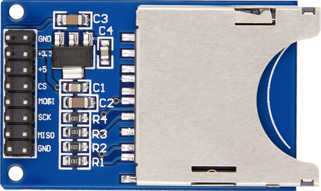
The SD-CARD-READER-2PINS is a simplified SD card reader module designed for easy integration into electronic projects. It allows for the reading and writing of data to a standard SD card using only two pins for communication. This component is ideal for applications where data logging, storage, or transfer is required, such as in embedded systems, data recorders, or IoT devices.
Explore Projects Built with SD-CARD-READER-2PINS
Arduino UNO SD Card Data Logger
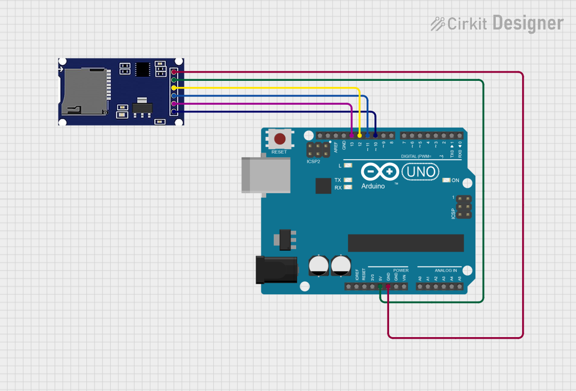
This circuit consists of an Arduino UNO connected to an SD card module. The Arduino provides power and ground to the SD module and interfaces with it using SPI communication through digital pins D10 (CS), D11 (MOSI), D12 (MISO), and D13 (SCK). The setup is intended for reading from or writing to an SD card using the Arduino.
Arduino UNO RFID Reader Interface Project
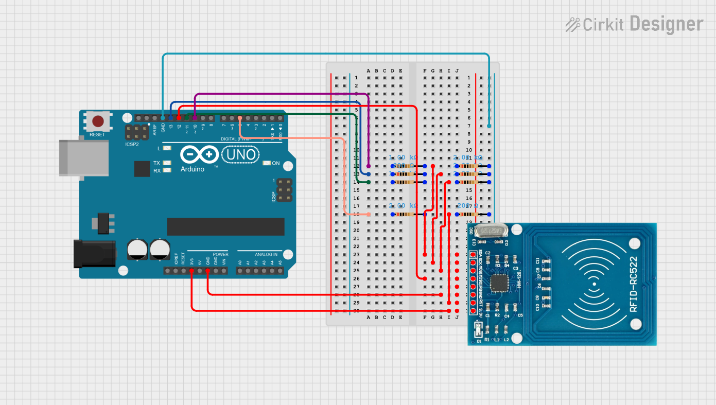
This is an RFID tag reading system. An Arduino UNO is interfaced with an RFID-RC522 module using digital pins D5, D10, D11, and D13 through resistors, with direct MISO connection to D12. The system is designed to read RFID tags and handle the data with the Arduino.
Arduino UNO R4 WiFi Controlled Data Logger with BNO055 Sensor and Micro SD Storage
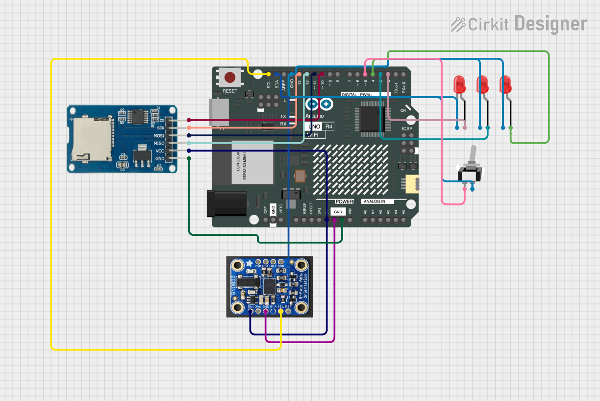
This circuit features an Arduino UNO R4 WiFi microcontroller connected to a Micro SD Card Module for data storage, a BNO055 sensor for orientation data, and three red LEDs for indication purposes. The LEDs are controlled by digital pins D2, D3, and D4, and can be turned on or off using a single-pole single-throw (SPST) toggle switch connected to their common cathodes and ground. The BNO055 sensor interfaces with the Arduino via I2C communication using the SDA and SCL pins, and the Micro SD Card Module is interfaced using SPI with chip select on pin D10 and data lines on pins D11 (MOSI), D12 (MISO), and D13 (SCK).
ESP32-Based RFID Reader with OLED Display
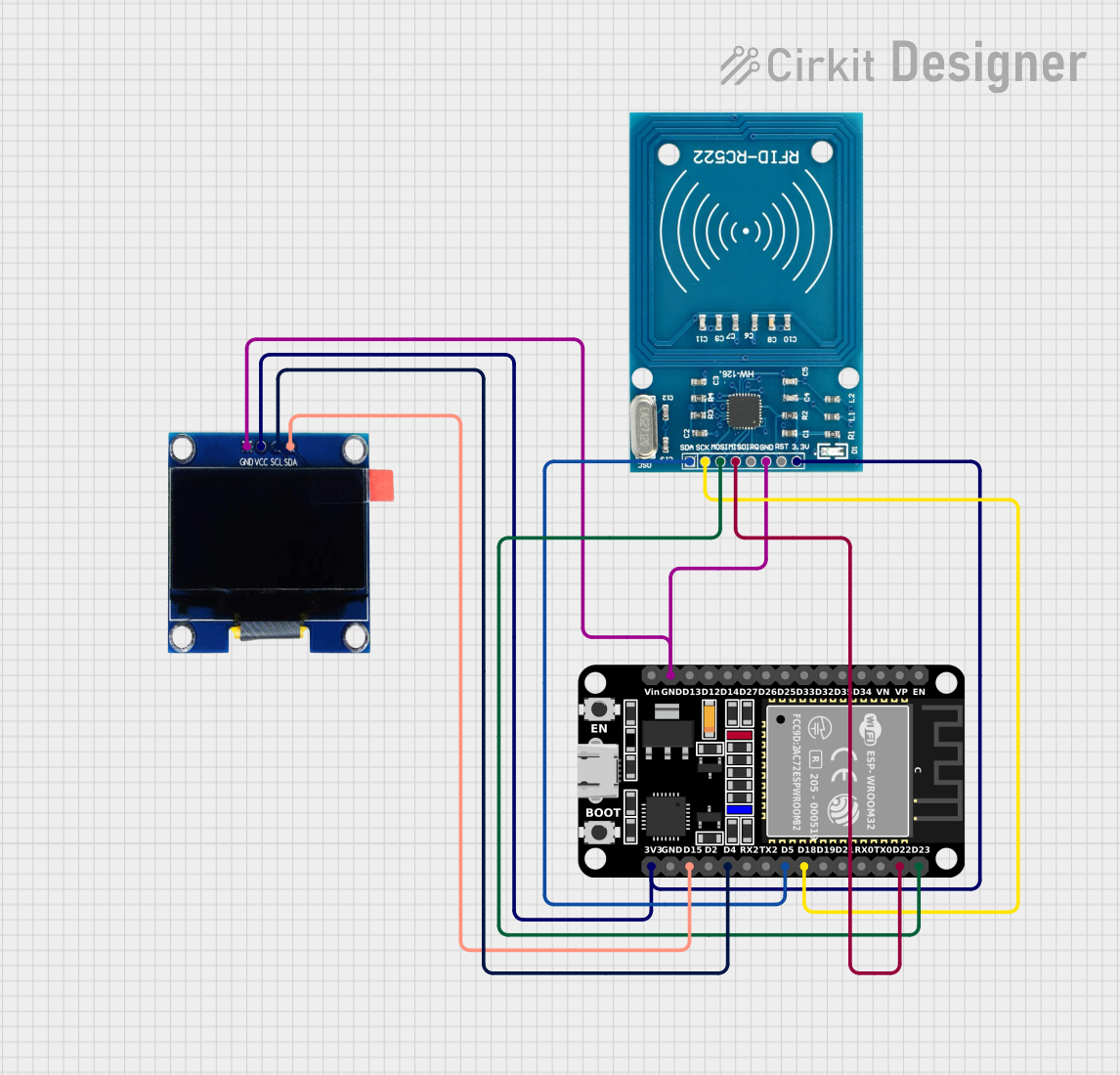
This circuit features an ESP32 microcontroller connected to an RFID-RC522 module and an OLED display. The ESP32 communicates with the RFID reader via SPI (using pins D23, D22, D18, and D5 for MOSI, MISO, SCK, and SDA respectively) and with the OLED display through I2C (using pins D4 and D15 for SCL and SDA). All devices share a common ground and are powered by the ESP32's 3.3V output, indicating the circuit is likely used for RFID tag reading and data display on the OLED.
Explore Projects Built with SD-CARD-READER-2PINS
Arduino UNO SD Card Data Logger
This circuit consists of an Arduino UNO connected to an SD card module. The Arduino provides power and ground to the SD module and interfaces with it using SPI communication through digital pins D10 (CS), D11 (MOSI), D12 (MISO), and D13 (SCK). The setup is intended for reading from or writing to an SD card using the Arduino.
Arduino UNO RFID Reader Interface Project
This is an RFID tag reading system. An Arduino UNO is interfaced with an RFID-RC522 module using digital pins D5, D10, D11, and D13 through resistors, with direct MISO connection to D12. The system is designed to read RFID tags and handle the data with the Arduino.
Arduino UNO R4 WiFi Controlled Data Logger with BNO055 Sensor and Micro SD Storage
This circuit features an Arduino UNO R4 WiFi microcontroller connected to a Micro SD Card Module for data storage, a BNO055 sensor for orientation data, and three red LEDs for indication purposes. The LEDs are controlled by digital pins D2, D3, and D4, and can be turned on or off using a single-pole single-throw (SPST) toggle switch connected to their common cathodes and ground. The BNO055 sensor interfaces with the Arduino via I2C communication using the SDA and SCL pins, and the Micro SD Card Module is interfaced using SPI with chip select on pin D10 and data lines on pins D11 (MOSI), D12 (MISO), and D13 (SCK).
ESP32-Based RFID Reader with OLED Display
This circuit features an ESP32 microcontroller connected to an RFID-RC522 module and an OLED display. The ESP32 communicates with the RFID reader via SPI (using pins D23, D22, D18, and D5 for MOSI, MISO, SCK, and SDA respectively) and with the OLED display through I2C (using pins D4 and D15 for SCL and SDA). All devices share a common ground and are powered by the ESP32's 3.3V output, indicating the circuit is likely used for RFID tag reading and data display on the OLED.
Common Applications and Use Cases
- Data logging for sensors
- Storing configuration or user data
- Audio and video storage for multimedia devices
- Firmware updates and storage for embedded systems
Technical Specifications
Key Technical Details
- Operating Voltage: 3.3V to 5V
- Communication: Serial Peripheral Interface (SPI) over 2 pins
- Supported SD card types: SD, SDHC (up to 32GB)
- Data transfer rate: Dependent on SD card speed class
Pin Configuration and Descriptions
| Pin Name | Description |
|---|---|
| VCC | Power supply (3.3V to 5V) |
| GND | Ground connection |
| DIO | Data Input/Output |
| CLK | Clock signal |
Usage Instructions
How to Use the Component in a Circuit
- Connect the VCC pin to the power supply (3.3V or 5V, depending on your circuit requirements).
- Connect the GND pin to the ground of your circuit.
- Connect the DIO pin to a digital I/O pin on your microcontroller.
- Connect the CLK pin to a clock output pin on your microcontroller.
Important Considerations and Best Practices
- Ensure that the power supply voltage matches the voltage requirements of the SD-CARD-READER-2PINS.
- Use a level shifter if your microcontroller operates at a different voltage level than the SD card reader.
- Format the SD card to the appropriate file system (usually FAT32) before use.
- Implement proper error handling in your code to manage read/write failures.
Example Code for Arduino UNO
#include <SPI.h>
#include <SD.h>

// Define the SPI pins for Arduino UNO
const int chipSelectPin = 10; // Chip select pin for SD card reader
const int cardDetectPin = 2;  // Card detect pin (optional)

void setup() {
  Serial.begin(9600);
  pinMode(chipSelectPin, OUTPUT);

  // Check for the presence of the SD card
  if (!SD.begin(chipSelectPin)) {
    Serial.println("Card failed, or not present");
    // Don't do anything more if the SD card is not present
    while (1);
  }
  Serial.println("Card initialized.");
}

void loop() {
  // Code to read or write data to the SD card
}
Note: The above code assumes that the SD-CARD-READER-2PINS uses the SPI interface with a chip select pin. Since the actual component has only two pins, the implementation may vary, and the code provided here is for illustrative purposes.
Troubleshooting and FAQs
Common Issues Users Might Face
- SD card not recognized: Ensure that the SD card is properly inserted and formatted.
- Read/Write errors: Check the connections and ensure that the correct pin assignments are used in the code.
- Corrupted data: Use proper file opening and closing practices to prevent data corruption.
Solutions and Tips for Troubleshooting
- Always power off the circuit before inserting or removing the SD card.
- Use a multimeter to verify that the power supply is within the specified range.
- If using a microcontroller at a different voltage level, ensure that a level shifter is used.
- Check the SD card for physical damage or try using a different SD card.
FAQs:
- Q: Can I use a microSD card with this reader?
- A: Yes, with an appropriate SD to microSD adapter.
- Q: What is the maximum storage capacity supported?
- A: The reader supports SD cards up to 32GB.
- Q: Does the reader support hot-swapping of SD cards?
- A: No, the SD card should be inserted or removed only when the power is off.