Cirkit Designer Logo
Cirkit Designer
Your all-in-one circuit design IDE
Home / 
Component Documentation

How to Use MAX7219 8x8 LED Matrix: Examples, Pinouts, and Specs

Image of MAX7219 8x8 LED Matrix
Cirkit Designer LogoDesign with MAX7219 8x8 LED Matrix in Cirkit Designer

Introduction

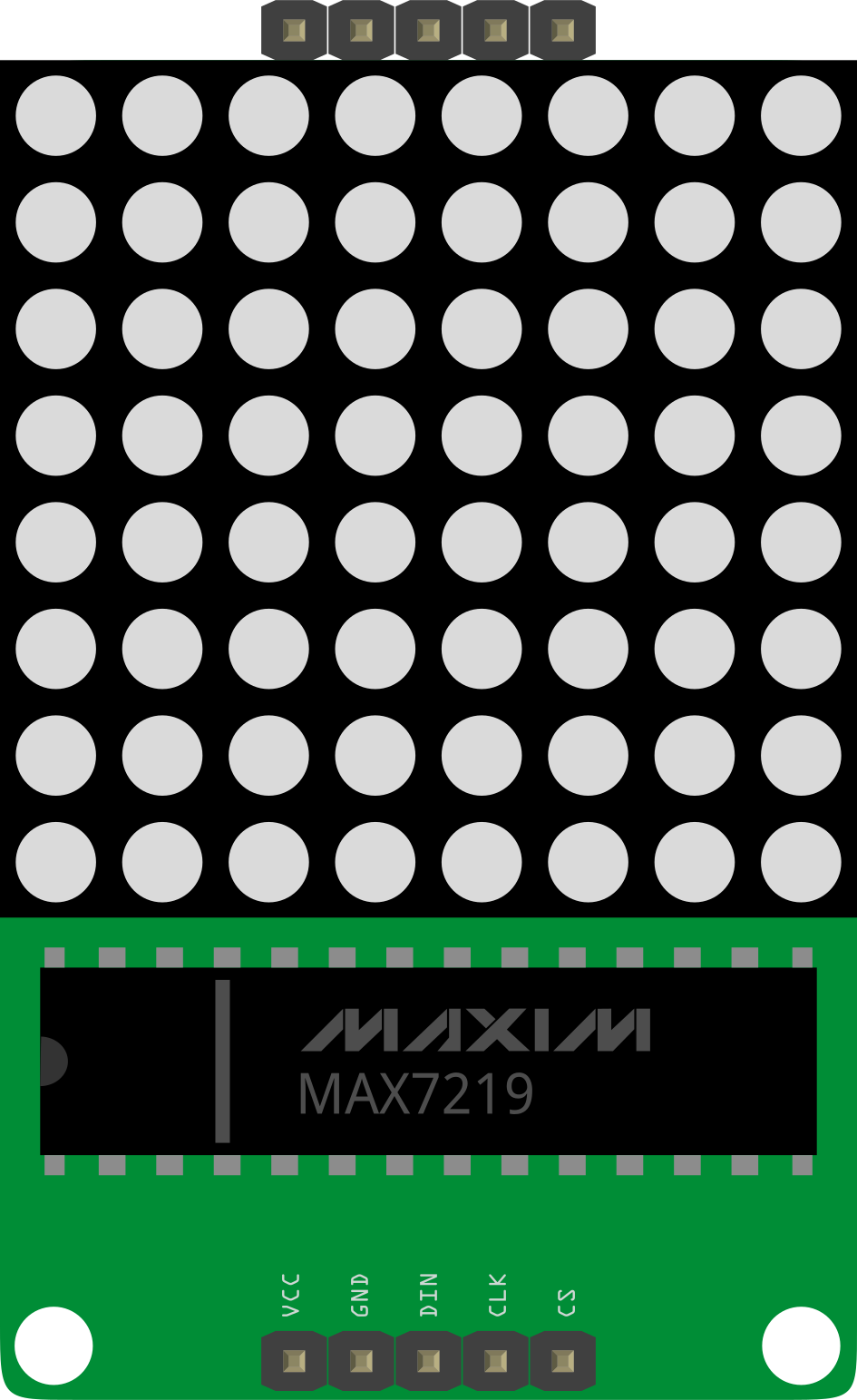
The MAX7219 8x8 LED Matrix is a compact and versatile display driver designed to control up to 64 individual LEDs arranged in an 8x8 matrix. This component simplifies the process of driving multiple LEDs by using a serial interface, which significantly reduces the number of microcontroller pins required. It is commonly used in creating display panels for visual output, digital clocks, electronic games, and other devices that require a simple yet effective graphical display.

Explore Projects Built with MAX7219 8x8 LED Matrix

Use Cirkit Designer to design, explore, and prototype these projects online. Some projects support real-time simulation. Click "Open Project" to start designing instantly!
Arduino UNO Controlled Multi-Matrix LED Display
Image of Test matrix with pixel moving: A project utilizing MAX7219 8x8 LED Matrix in a practical application
This circuit consists of an Arduino UNO microcontroller connected to multiple MAX7219 8x8 LED Matrix modules arranged in a daisy-chain configuration. The Arduino controls the LED matrices using a software-implemented SPI communication protocol, with the purpose of displaying complex patterns or animations across the combined matrix display. The provided code handles the initialization and updating of the LED matrices, creating visual effects by manipulating the framebuffer and sending the data to the LED matrices in the correct order.
Cirkit Designer LogoOpen Project in Cirkit Designer
Arduino UNO Controlled 8x8 LED Matrix Display
Image of LED: A project utilizing MAX7219 8x8 LED Matrix in a practical application
This circuit consists of an Arduino UNO microcontroller connected to a MAX7219 8x8 LED Matrix. The Arduino controls the LED matrix by sending data through digital pins D10, D11, and D13, while power and ground connections are provided by the 5V and GND pins, respectively.
Cirkit Designer LogoOpen Project in Cirkit Designer
ESP32-Based Smart Weather Station with LED Display and Multiple Sensors
Image of Copy of Zegarek (1): A project utilizing MAX7219 8x8 LED Matrix in a practical application
This circuit is a sensor and display system powered by an ESP32 microcontroller. It integrates multiple sensors (BH1750 light sensor, BMP280 pressure sensor, DS3231 RTC, and DS18B20 temperature sensor) and drives a series of MAX7219 8x8 LED matrices for visual output. The ESP32 communicates with the sensors via I2C and controls the LED matrices to display data.
Cirkit Designer LogoOpen Project in Cirkit Designer
Arduino UNO-Based IR Sensor and LED Matrix Display System
Image of max: A project utilizing MAX7219 8x8 LED Matrix in a practical application
This circuit uses an Arduino UNO to control two MAX7219 8x8 LED matrices and an IR sensor. The Arduino reads input from the IR sensor and drives the LED matrices, likely for displaying patterns or messages based on the sensor input.
Cirkit Designer LogoOpen Project in Cirkit Designer

Explore Projects Built with MAX7219 8x8 LED Matrix

Use Cirkit Designer to design, explore, and prototype these projects online. Some projects support real-time simulation. Click "Open Project" to start designing instantly!
Image of Test matrix with pixel moving: A project utilizing MAX7219 8x8 LED Matrix in a practical application
Arduino UNO Controlled Multi-Matrix LED Display
This circuit consists of an Arduino UNO microcontroller connected to multiple MAX7219 8x8 LED Matrix modules arranged in a daisy-chain configuration. The Arduino controls the LED matrices using a software-implemented SPI communication protocol, with the purpose of displaying complex patterns or animations across the combined matrix display. The provided code handles the initialization and updating of the LED matrices, creating visual effects by manipulating the framebuffer and sending the data to the LED matrices in the correct order.
Cirkit Designer LogoOpen Project in Cirkit Designer
Image of LED: A project utilizing MAX7219 8x8 LED Matrix in a practical application
Arduino UNO Controlled 8x8 LED Matrix Display
This circuit consists of an Arduino UNO microcontroller connected to a MAX7219 8x8 LED Matrix. The Arduino controls the LED matrix by sending data through digital pins D10, D11, and D13, while power and ground connections are provided by the 5V and GND pins, respectively.
Cirkit Designer LogoOpen Project in Cirkit Designer
Image of Copy of Zegarek (1): A project utilizing MAX7219 8x8 LED Matrix in a practical application
ESP32-Based Smart Weather Station with LED Display and Multiple Sensors
This circuit is a sensor and display system powered by an ESP32 microcontroller. It integrates multiple sensors (BH1750 light sensor, BMP280 pressure sensor, DS3231 RTC, and DS18B20 temperature sensor) and drives a series of MAX7219 8x8 LED matrices for visual output. The ESP32 communicates with the sensors via I2C and controls the LED matrices to display data.
Cirkit Designer LogoOpen Project in Cirkit Designer
Image of max: A project utilizing MAX7219 8x8 LED Matrix in a practical application
Arduino UNO-Based IR Sensor and LED Matrix Display System
This circuit uses an Arduino UNO to control two MAX7219 8x8 LED matrices and an IR sensor. The Arduino reads input from the IR sensor and drives the LED matrices, likely for displaying patterns or messages based on the sensor input.
Cirkit Designer LogoOpen Project in Cirkit Designer

Common Applications and Use Cases

  • Digital scoreboards
  • Clock displays
  • Message boards
  • Gaming displays
  • Interactive art installations

Technical Specifications

Key Technical Details

  • Operating Voltage: 4.0V to 5.5V
  • Maximum Current: 500mA (when all LEDs are on)
  • Display Drive: Common cathode
  • Interface: Serial (SPI-compatible)

Pin Configuration and Descriptions

Pin Number Name Description
1 VCC Power supply (4.0V to 5.5V)
2 GND Ground
3 DIN Serial-Data Input
4 CS Chip Select (active low)
5 CLK Serial-Clock Input
6-13 SEG A-G, DP Segment and decimal point control for each digit
14-21 DIG 0-7 Digit drive lines (common cathode)

Usage Instructions

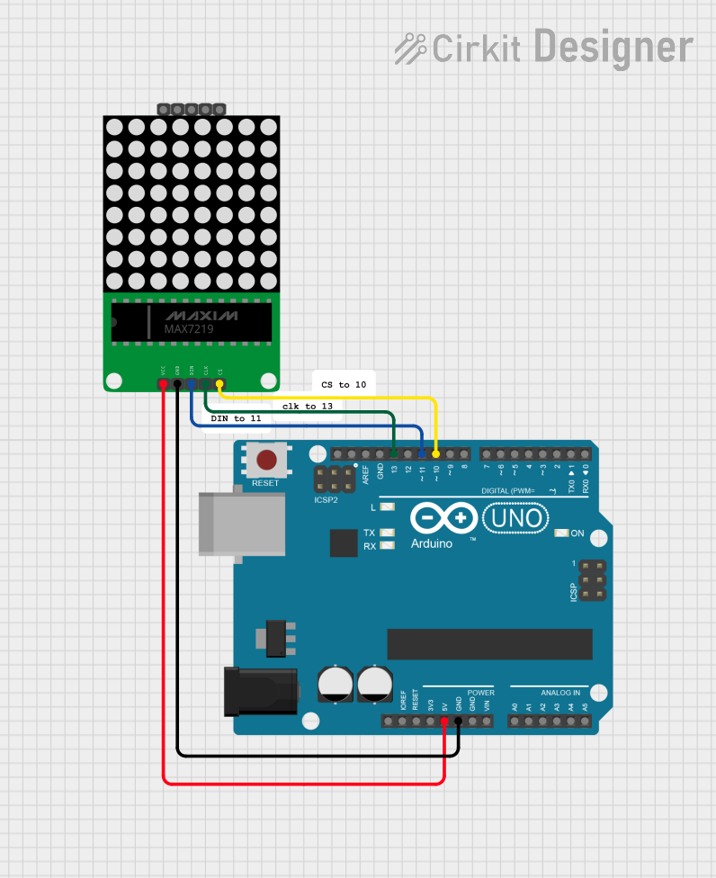
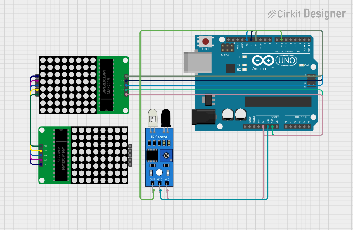
How to Use the Component in a Circuit

  1. Power Connections: Connect VCC to a 5V power supply and GND to the ground.
  2. Data Input: Connect the DIN, CS, and CLK pins to the microcontroller's SPI pins.
  3. LED Matrix: Connect the SEG and DIG pins to the corresponding pins on the 8x8 LED matrix.

Important Considerations and Best Practices

  • Use a current-limiting resistor to prevent damage to the LEDs.
  • Ensure that the power supply can handle the maximum current draw when all LEDs are on.
  • Avoid long wires between the MAX7219 and the LED matrix to minimize signal degradation.
  • Implement proper decoupling with a capacitor close to the VCC and GND pins of the MAX7219.

Example Code for Arduino UNO

#include <LedControl.h>

// Pin configuration for the MAX7219
int DIN_PIN = 2;
int CS_PIN = 3;
int CLK_PIN = 4;

// Create a new LedControl instance
LedControl lc = LedControl(DIN_PIN, CLK_PIN, CS_PIN, 1);

void setup() {
  // Wake up the MAX7219 from power-saving mode
  lc.shutdown(0, false);
  // Set brightness level (0 is min, 15 is max)
  lc.setIntensity(0, 8);
  // Clear the display
  lc.clearDisplay(0);
}

void loop() {
  // Display a simple pattern on the LED matrix
  for (int row = 0; row < 8; row++) {
    for (int col = 0; col < 8; col++) {
      lc.setLed(0, row, col, true); // Turn on LED at (row, col)
      delay(200);
      lc.setLed(0, row, col, false); // Turn off LED at (row, col)
    }
  }
}

Troubleshooting and FAQs

Common Issues

  • All LEDs are dim or flickering: Check the power supply and ensure it can provide sufficient current.
  • Some LEDs are not lighting up: Verify the wiring between the MAX7219 and the LED matrix, and check for any damaged LEDs.
  • Garbled or incorrect display: Ensure that the SPI communication is functioning correctly and that there are no loose connections.

Solutions and Tips for Troubleshooting

  • Double-check all connections, especially the DIN, CS, and CLK lines.
  • Use a multimeter to verify that the correct voltage is present at the VCC pin.
  • Replace the LED matrix if you suspect it has damaged LEDs.
  • Ensure that the microcontroller's SPI settings match the requirements of the MAX7219.

FAQs

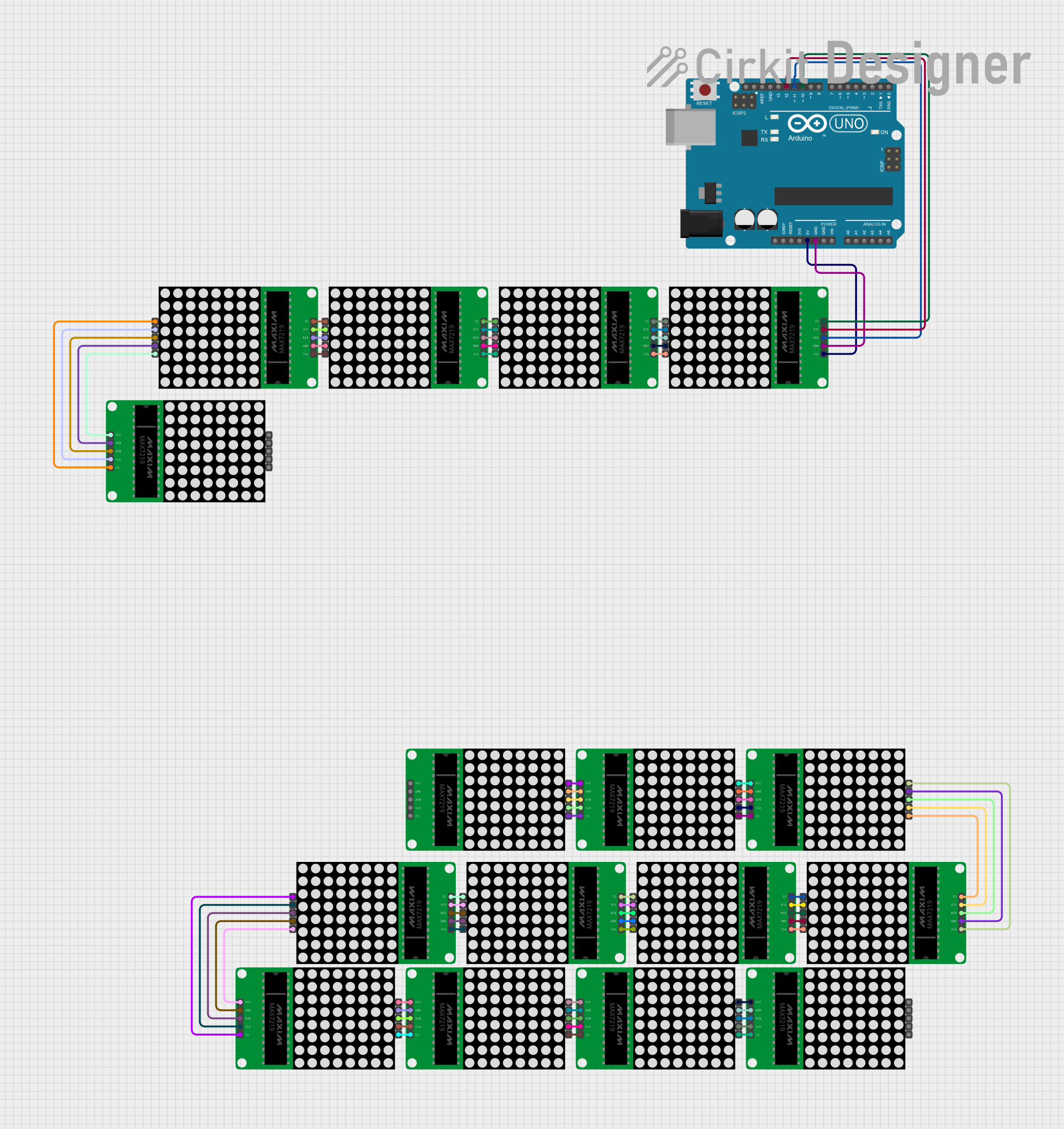
Q: Can I daisy-chain multiple MAX7219 modules? A: Yes, the MAX7219 is designed to be daisy-chained. Connect the DOUT of the first module to the DIN of the next, and so on.

Q: How do I control the brightness of the LEDs? A: Use the setIntensity() function in the LedControl library to adjust the brightness level.

Q: What is the maximum number of devices I can control with a single microcontroller? A: Theoretically, you can control as many devices as the microcontroller's memory can handle, but practical limits are set by the power supply and signal integrity over long daisy chains.