How to Use MDDRC10 10Amp 7V-30V DC Motor Driver for R/C (2 Channels): Examples, Pinouts, and Specs
Introduction
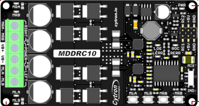
The MDDRC10 is a dual-channel DC motor driver manufactured by Cytron, designed to control two DC motors with a current rating of up to 10 Amps per channel. It operates within a voltage range of 7V to 30V, making it suitable for a wide variety of applications. This motor driver is specifically optimized for remote-controlled (R/C) systems, offering seamless integration with standard R/C receivers.
Explore Projects Built with MDDRC10 10Amp 7V-30V DC Motor Driver for R/C (2 Channels)


Explore Projects Built with MDDRC10 10Amp 7V-30V DC Motor Driver for R/C (2 Channels)
Common Applications and Use Cases
- Remote-controlled vehicles (e.g., cars, boats, and robots)
- DIY robotics projects
- Automation systems requiring precise motor control
- Educational and prototyping purposes
Technical Specifications
Key Technical Details
| Parameter | Specification |
|---|---|
| Manufacturer | Cytron |
| Part ID | MDDRC10 |
| Operating Voltage Range | 7V to 30V |
| Continuous Current | 10A per channel |
| Peak Current | 30A per channel (for 10 seconds) |
| Control Signal Input | Standard R/C PWM signal |
| PWM Frequency | 50Hz to 330Hz |
| Motor Channels | 2 |
| Dimensions | 84mm x 62mm x 18mm |
| Weight | 80g |
Pin Configuration and Descriptions
The MDDRC10 features a set of connectors for power, motor outputs, and control signals. Below is the pin configuration:
Power and Motor Output
| Pin/Connector | Description |
|---|---|
| VIN+ | Positive terminal for power input |
| VIN- | Negative terminal (ground) for power input |
| M1+ | Positive terminal for Motor 1 |
| M1- | Negative terminal for Motor 1 |
| M2+ | Positive terminal for Motor 2 |
| M2- | Negative terminal for Motor 2 |
Control Signal Input
| Pin/Connector | Description |
|---|---|
| CH1 | PWM signal input for Motor 1 |
| CH2 | PWM signal input for Motor 2 |
| GND | Ground for control signal |
Usage Instructions
How to Use the MDDRC10 in a Circuit
- Power Supply: Connect a DC power source (7V to 30V) to the
VIN+andVIN-terminals. Ensure the power supply can handle the current requirements of the motors. - Motor Connections: Connect the DC motors to the
M1+/M1-andM2+/M2-terminals. Ensure the polarity matches your desired motor direction. - Control Signal: Connect the
CH1andCH2pins to the PWM signal outputs of your R/C receiver or microcontroller. Use theGNDpin to establish a common ground. - Operation: Send PWM signals to the
CH1andCH2pins to control the speed and direction of the motors. A neutral PWM signal (e.g., 1500µs) stops the motor, while higher or lower signals control forward or reverse motion.
Important Considerations and Best Practices
- Heat Dissipation: The MDDRC10 can handle high currents, but prolonged operation at peak current may cause overheating. Use proper ventilation or a heatsink if necessary.
- Power Supply: Ensure the power supply voltage matches the motor's operating range and the MDDRC10's input range.
- Signal Compatibility: The MDDRC10 is designed for standard R/C PWM signals. If using a microcontroller, ensure the PWM frequency is within the supported range (50Hz to 330Hz).
- Polarity: Double-check all connections to avoid damage due to reverse polarity.
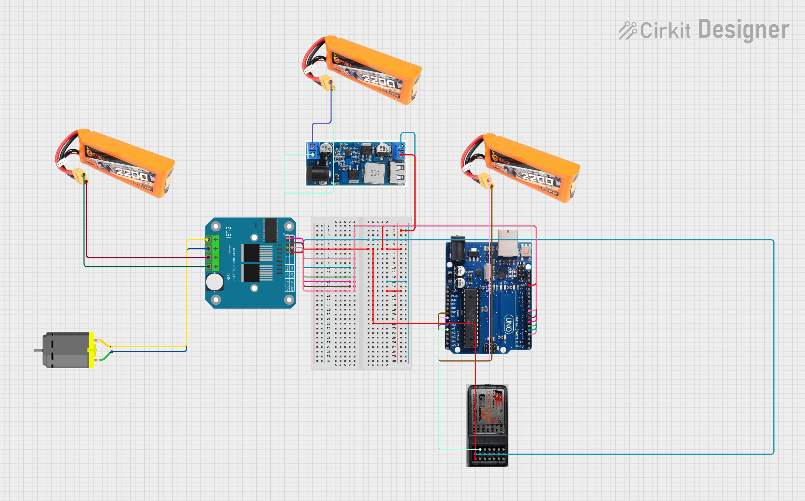
Example: Using MDDRC10 with Arduino UNO
Below is an example of controlling the MDDRC10 with an Arduino UNO:
// Example code to control MDDRC10 with Arduino UNO
// This code generates PWM signals for two motors connected to MDDRC10

#include <Servo.h> // Library to generate R/C PWM signals

Servo motor1; // Create Servo object for Motor 1
Servo motor2; // Create Servo object for Motor 2

void setup() {
  motor1.attach(9); // Attach Motor 1 control to pin 9
  motor2.attach(10); // Attach Motor 2 control to pin 10

  // Set both motors to neutral (stop)
  motor1.writeMicroseconds(1500); // Neutral signal for Motor 1
  motor2.writeMicroseconds(1500); // Neutral signal for Motor 2
}

void loop() {
  // Example: Move Motor 1 forward and Motor 2 backward
  motor1.writeMicroseconds(1700); // Forward signal for Motor 1
  motor2.writeMicroseconds(1300); // Reverse signal for Motor 2

  delay(2000); // Run motors for 2 seconds

  // Stop both motors
  motor1.writeMicroseconds(1500); // Neutral signal for Motor 1
  motor2.writeMicroseconds(1500); // Neutral signal for Motor 2

  delay(2000); // Wait for 2 seconds
}
Troubleshooting and FAQs
Common Issues and Solutions
Motors Not Running
- Cause: Incorrect PWM signal or no signal.
- Solution: Verify the PWM signal source and ensure it is within the supported range (50Hz to 330Hz). Check the connections to the
CH1andCH2pins.
Overheating
- Cause: Prolonged operation at high current or insufficient ventilation.
- Solution: Reduce the motor load or improve cooling with a heatsink or fan.
Motor Running in the Wrong Direction
- Cause: Incorrect motor polarity.
- Solution: Swap the connections on the
M1+/M1-orM2+/M2-terminals.
No Power to the Motor Driver
- Cause: Incorrect power supply connection or insufficient voltage.
- Solution: Verify the power supply voltage and polarity. Ensure the power source can provide sufficient current.
FAQs
Can I use the MDDRC10 with a microcontroller other than Arduino? Yes, as long as the microcontroller can generate standard R/C PWM signals within the supported frequency range.
What happens if I exceed the 10A continuous current rating? The motor driver may overheat or shut down to protect itself. Prolonged operation beyond the rated current can damage the driver.
Can I control only one motor with the MDDRC10? Yes, you can use a single channel (CH1 or CH2) to control one motor while leaving the other channel unused.
Is the MDDRC10 compatible with brushless motors? No, the MDDRC10 is designed for brushed DC motors only.