Cirkit Designer
Your all-in-one circuit design IDE
Home /
Component Documentation
How to Use MT3608: Examples, Pinouts, and Specs
Introduction
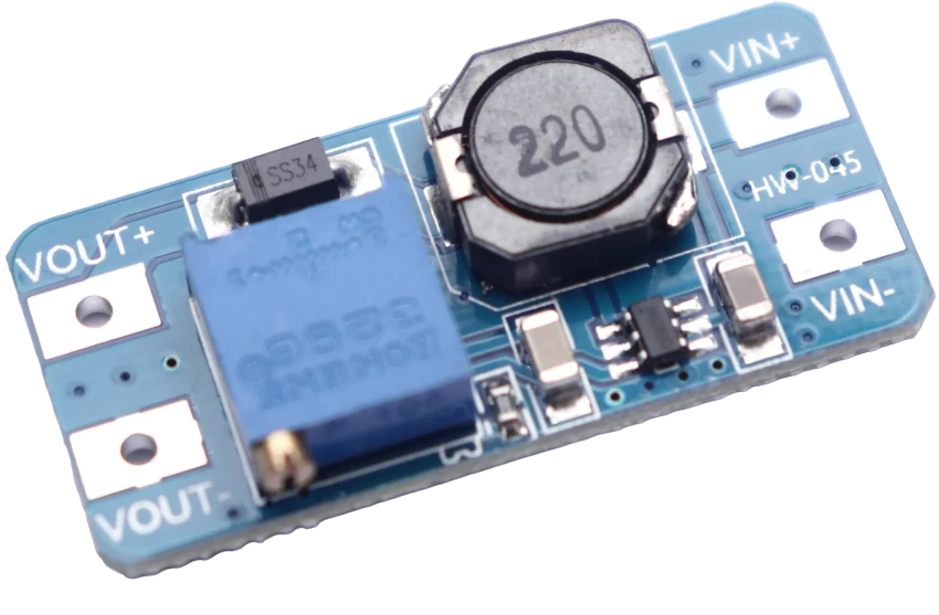
The MT3608 is a highly efficient, step-up (boost) DC-DC converter module designed to increase the voltage from a lower voltage source to a higher voltage as required by the load. It is commonly used in battery-powered devices, portable electronics, and power supply designs where a higher voltage level is needed from a lower voltage source.
Explore Projects Built with MT3608
ESP32-Controlled Bluetooth Robotic Vehicle with MT3608 Boost Converters and L298N Motor Drivers
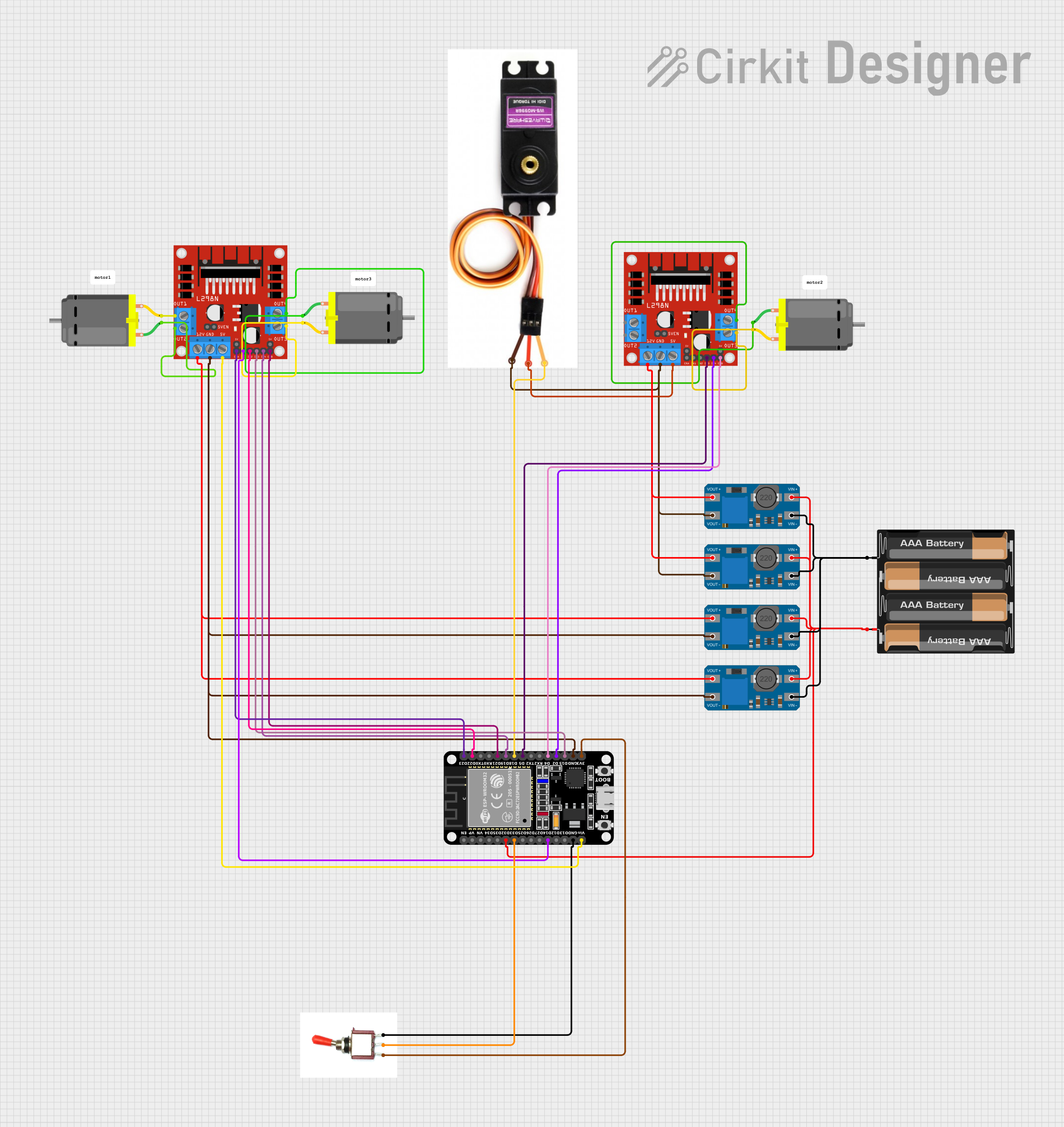
This circuit is designed to control multiple DC motors and a servo motor using an ESP32 microcontroller, which is interfaced with Bluetooth for wireless control commands. The ESP32 outputs control signals to two L298N motor drivers, which in turn drive the DC motors. The MT3608 modules are used to step up the voltage from a 4 x AAA battery mount to power the motor drivers, while the servo motor is directly controlled by the ESP32.
Voltage Regulation System with MT3608 Boost and LM2596 Buck Converters

This circuit consists of two MT3608 boost converters and an LM2596 step-down module, each connected to separate 12V power supplies. The MT3608 modules are configured to step up the voltage from their respective power supplies, while the LM2596 module steps down the voltage from a 12V battery. Diodes are used to ensure correct current flow direction, potentially for protection or isolation between different parts of the circuit.
ESP32-Powered Obstacle Avoidance Robot with IR and Ultrasonic Sensors

This circuit features a 18650 Li-Ion battery connected to a TP4056 charging module, which in turn is connected to an MT3608 boost converter to step up the voltage. The output of the MT3608 powers an ESP32 microcontroller, a TCRT 5000 IR sensor, an HC-SR04 ultrasonic sensor, and an MG996R servo motor. The ESP32 is configured to control the servo motor via GPIO 27 and to receive input signals from the IR sensor and ultrasonic sensor through GPIO 14 and GPIO 13, respectively.
ESP32-Controlled Traffic Light and DC Motors with MT3608 Boost Converters

This circuit is designed to control a traffic light and multiple DC motors using an ESP32 microcontroller. The ESP32's GPIO pins are connected to the traffic light to control the green, yellow, and red LEDs, and to the L298N motor drivers for controlling the speed and direction of the DC motors. The MT3608 modules are used to step up the voltage from the AAA batteries to power the motor drivers, and the MG996R servo is controlled by the ESP32 for additional actuation tasks.
Explore Projects Built with MT3608
ESP32-Controlled Bluetooth Robotic Vehicle with MT3608 Boost Converters and L298N Motor Drivers
This circuit is designed to control multiple DC motors and a servo motor using an ESP32 microcontroller, which is interfaced with Bluetooth for wireless control commands. The ESP32 outputs control signals to two L298N motor drivers, which in turn drive the DC motors. The MT3608 modules are used to step up the voltage from a 4 x AAA battery mount to power the motor drivers, while the servo motor is directly controlled by the ESP32.
Voltage Regulation System with MT3608 Boost and LM2596 Buck Converters
This circuit consists of two MT3608 boost converters and an LM2596 step-down module, each connected to separate 12V power supplies. The MT3608 modules are configured to step up the voltage from their respective power supplies, while the LM2596 module steps down the voltage from a 12V battery. Diodes are used to ensure correct current flow direction, potentially for protection or isolation between different parts of the circuit.
ESP32-Powered Obstacle Avoidance Robot with IR and Ultrasonic Sensors
This circuit features a 18650 Li-Ion battery connected to a TP4056 charging module, which in turn is connected to an MT3608 boost converter to step up the voltage. The output of the MT3608 powers an ESP32 microcontroller, a TCRT 5000 IR sensor, an HC-SR04 ultrasonic sensor, and an MG996R servo motor. The ESP32 is configured to control the servo motor via GPIO 27 and to receive input signals from the IR sensor and ultrasonic sensor through GPIO 14 and GPIO 13, respectively.
ESP32-Controlled Traffic Light and DC Motors with MT3608 Boost Converters
This circuit is designed to control a traffic light and multiple DC motors using an ESP32 microcontroller. The ESP32's GPIO pins are connected to the traffic light to control the green, yellow, and red LEDs, and to the L298N motor drivers for controlling the speed and direction of the DC motors. The MT3608 modules are used to step up the voltage from the AAA batteries to power the motor drivers, and the MG996R servo is controlled by the ESP32 for additional actuation tasks.
Common Applications and Use Cases
- Powering circuits that require a voltage higher than the battery supply
- Portable electronic devices
- Driving LED arrays
- Small power amplifiers
- Microcontroller projects, including Arduino-based designs
Technical Specifications
Key Technical Details
- Input Voltage Range: 2V to 24V
- Maximum Output Voltage: 28V (adjustable via onboard potentiometer)
- Maximum Switching Current: 2A
- Efficiency: Up to 93%
- Switching Frequency: 1.2MHz
- Operating Temperature: -40°C to +85°C
Pin Configuration and Descriptions
| Pin Number | Name | Description |
|---|---|---|
| 1 | VIN | Input voltage to the module (2V to 24V) |
| 2 | GND | Ground reference for the module |
| 3 | VOUT | Output voltage from the module (up to 28V) |
| 4 | GND | Ground reference for the output |
Usage Instructions
How to Use the MT3608 in a Circuit
- Connect the input voltage (2V to 24V) to the VIN and GND pins.
- Adjust the onboard potentiometer to set the desired output voltage. Use a multimeter to measure the output voltage while adjusting.
- Connect the load to the VOUT and GND pins.
- Ensure that the load does not exceed the maximum current rating of 2A.
Important Considerations and Best Practices
- Always start with the potentiometer turned fully counterclockwise to set the lowest output voltage before applying power.
- Gradually increase the output voltage to the desired level while monitoring with a multimeter.
- Do not exceed the input voltage range or the maximum output current to prevent damage to the module.
- Provide adequate cooling if the module is expected to operate near its maximum ratings.
- Use capacitors at the input and output for better voltage regulation and to reduce noise.
Troubleshooting and FAQs
Common Issues Users Might Face
- Output voltage does not reach the desired level: Ensure that the input voltage is sufficient and that the potentiometer is adjusted correctly.
- Module overheats: Check if the current draw is within the module's limit and improve cooling if necessary.
- No output voltage: Verify connections and input voltage, and ensure that the module is not damaged.
Solutions and Tips for Troubleshooting
- If the output voltage is unstable or too low, check the input voltage and the load to ensure they are within specifications.
- If the module is overheating, reduce the load or improve heat dissipation.
- In case of no output, recheck all connections, ensure the input voltage is present, and that the potentiometer is adjusted properly.
Example Code for Arduino UNO
// This example demonstrates how to use the MT3608 with an Arduino to power an LED strip.

const int ledPin = 9; // Connect the LED strip to pin 9 (PWM capable)

void setup() {
  pinMode(ledPin, OUTPUT);
  // Start with the LED strip off
  analogWrite(ledPin, 0);
}

void loop() {
  // Gradually turn on the LED strip
  for (int i = 0; i <= 255; i++) {
    analogWrite(ledPin, i);
    delay(10); // Short delay to see the dimming effect
  }
  // Gradually turn off the LED strip
  for (int i = 255; i >= 0; i--) {
    analogWrite(ledPin, i);
    delay(10); // Short delay to see the dimming effect
  }
}
Note: The above code assumes that the MT3608 module is used to step up the voltage to a level suitable for driving an LED strip and that the Arduino is used to control the brightness via PWM. Always ensure that the output voltage from the MT3608 is appropriate for the LED strip being used.