
How to Use ADXL327 3-Axis Accelerometer on DIP Adapter: Examples, Pinouts, and Specs
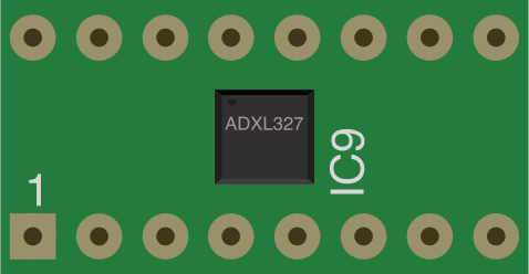
 Design with ADXL327 3-Axis Accelerometer on DIP Adapter in Cirkit Designer
Introduction
The ADXL327 is a low-power, 3-axis accelerometer capable of measuring acceleration in three dimensions (X, Y, and Z axes). It is designed for applications requiring motion sensing, tilt detection, and vibration monitoring. The device outputs analog voltage signals proportional to the acceleration experienced along each axis.
The DIP adapter simplifies integration into breadboards and prototyping setups, making it ideal for rapid development and testing. Common applications include:
- Tilt sensing in portable devices
- Vibration monitoring in industrial equipment
- Motion detection in robotics and gaming peripherals
- Impact detection in safety systems
Explore Projects Built with ADXL327 3-Axis Accelerometer on DIP Adapter
 Open Project in Cirkit Designer
 Open Project in Cirkit Designer
 Open Project in Cirkit Designer
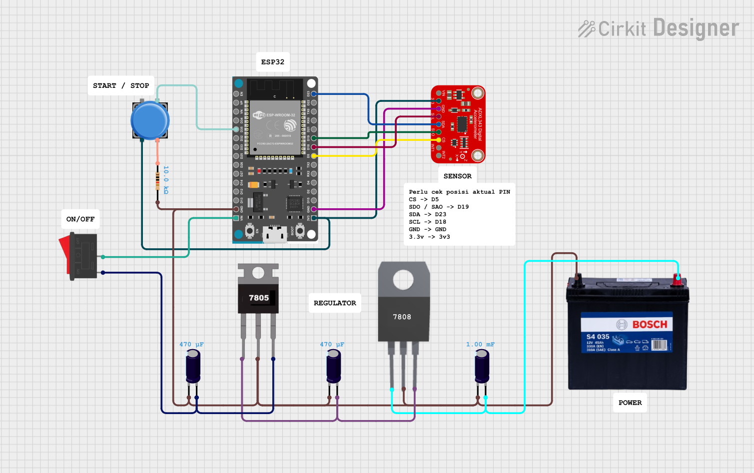 Open Project in Cirkit Designer
Explore Projects Built with ADXL327 3-Axis Accelerometer on DIP Adapter
Open Project in Cirkit DesignerOpen Project in Cirkit DesignerOpen Project in Cirkit DesignerOpen Project in Cirkit DesignerTechnical Specifications
The ADXL327 is a robust and versatile accelerometer with the following key specifications:
| Parameter | Value |
|---|---|
| Supply Voltage (VDD) | 1.8 V to 3.6 V |
| Typical Supply Current | 300 µA |
| Measurement Range | ±2 g |
| Sensitivity | 420 mV/g |
| Bandwidth | Configurable (0.5 Hz to 1600 Hz) |
| Output Type | Analog voltage |
| Operating Temperature Range | -40°C to +85°C |
| Dimensions (DIP Adapter) | 0.8" x 0.6" |
Pin Configuration and Descriptions
The ADXL327 on the DIP adapter has a total of 6 pins. The table below describes each pin:
| Pin | Name | Description |
|---|---|---|
| 1 | VDD | Power supply input (1.8 V to 3.6 V). Connect to the positive terminal of the power source. |
| 2 | GND | Ground. Connect to the ground of the circuit. |
| 3 | XOUT | Analog output voltage proportional to acceleration along the X-axis. |
| 4 | YOUT | Analog output voltage proportional to acceleration along the Y-axis. |
| 5 | ZOUT | Analog output voltage proportional to acceleration along the Z-axis. |
| 6 | ST | Self-test pin. Apply a voltage to enable the self-test feature. |
Usage Instructions
How to Use the ADXL327 in a Circuit
- Power the Device: Connect the VDD pin to a 3.3 V power source (or any voltage within the 1.8 V to 3.6 V range). Connect the GND pin to the ground of your circuit.
- Connect the Outputs: Use the XOUT, YOUT, and ZOUT pins to read the analog voltage signals corresponding to the acceleration along each axis. These outputs can be connected to an ADC (Analog-to-Digital Converter) for digital processing.
- Optional Self-Test: To verify the functionality of the accelerometer, apply a voltage to the ST pin. Refer to the datasheet for the specific voltage required for self-test operation.
Important Considerations and Best Practices
- Decoupling Capacitors: Place a 0.1 µF ceramic capacitor close to the VDD pin to reduce noise and ensure stable operation.
- Bandwidth Configuration: Use external capacitors on the XOUT, YOUT, and ZOUT pins to set the desired bandwidth. Refer to the datasheet for recommended capacitor values.
- Mounting Orientation: Ensure the accelerometer is mounted securely and aligned correctly for accurate measurements.
- Signal Conditioning: If the output signals are noisy, consider adding low-pass filters to smooth the signals.
Example: Connecting to an Arduino UNO
The ADXL327 can be easily interfaced with an Arduino UNO to read acceleration data. Below is an example code snippet:
// Define the analog input pins for the ADXL327 outputs
const int xPin = A0; // XOUT connected to A0
const int yPin = A1; // YOUT connected to A1
const int zPin = A2; // ZOUT connected to A2

void setup() {
  // Initialize serial communication for debugging
  Serial.begin(9600);
}

void loop() {
  // Read the analog values from the ADXL327
  int xValue = analogRead(xPin); // Read X-axis acceleration
  int yValue = analogRead(yPin); // Read Y-axis acceleration
  int zValue = analogRead(zPin); // Read Z-axis acceleration

  // Convert the analog values to voltage (assuming 5V reference)
  float xVoltage = xValue * (5.0 / 1023.0);
  float yVoltage = yValue * (5.0 / 1023.0);
  float zVoltage = zValue * (5.0 / 1023.0);

  // Print the voltage values to the Serial Monitor
  Serial.print("X Voltage: ");
  Serial.print(xVoltage);
  Serial.print(" V, Y Voltage: ");
  Serial.print(yVoltage);
  Serial.print(" V, Z Voltage: ");
  Serial.print(zVoltage);
  Serial.println(" V");

  // Delay for a short period to avoid flooding the Serial Monitor
  delay(500);
}
Notes:
- Ensure the Arduino's analog reference voltage matches the ADXL327's output voltage range for accurate readings.
- Adjust the
delay()value in the code to control the data sampling rate.
Troubleshooting and FAQs
Common Issues and Solutions
No Output Signal:
- Verify that the VDD and GND pins are properly connected.
- Check the power supply voltage to ensure it is within the specified range (1.8 V to 3.6 V).
Noisy Output:
- Add decoupling capacitors near the power supply pins.
- Use external capacitors on the output pins to limit the bandwidth and reduce noise.
Incorrect Readings:
- Ensure the accelerometer is mounted securely and aligned correctly.
- Verify that the ADC reference voltage matches the expected range of the ADXL327's output.
Self-Test Not Working:
- Confirm the correct voltage is applied to the ST pin as specified in the datasheet.
- Ensure the self-test feature is enabled only when needed.
FAQs
Q: Can the ADXL327 measure static acceleration (e.g., gravity)?
A: Yes, the ADXL327 can measure both static acceleration (e.g., tilt due to gravity) and dynamic acceleration (e.g., motion or vibration).
Q: What is the maximum sampling rate for the ADXL327?
A: The maximum bandwidth is 1600 Hz, which corresponds to a maximum sampling rate of 3200 samples per second.
Q: Can I use the ADXL327 with a 5 V microcontroller?
A: Yes, but you must ensure the ADXL327 is powered within its specified range (1.8 V to 3.6 V). Use a voltage regulator or level shifter if necessary.
Q: How do I set the bandwidth of the ADXL327?
A: The bandwidth is set using external capacitors connected to the XOUT, YOUT, and ZOUT pins. Refer to the datasheet for recommended capacitor values for specific bandwidths.