How to Use DC-DC Power converter with display: Examples, Pinouts, and Specs
Introduction
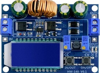
The AZDelivery HW-140 is a versatile DC-DC power converter designed to convert a source of direct current (DC) from one voltage level to another. This component is particularly useful in applications where different parts of a system require different voltage levels. The integrated display allows for real-time monitoring of output voltage and current, making it an excellent choice for both hobbyists and professionals.
Explore Projects Built with DC-DC Power converter with display


Explore Projects Built with DC-DC Power converter with display
Common Applications and Use Cases
- Battery-Powered Projects: Adjusting voltage levels to match the requirements of different components.
- Arduino Projects: Providing stable voltage to microcontrollers and sensors.
- Portable Electronics: Powering devices with varying voltage needs from a single battery source.
- Prototyping and Testing: Easily adjusting voltage levels for different test scenarios.
Technical Specifications
Key Technical Details
| Parameter | Value |
|---|---|
| Input Voltage Range | 4.0V to 40V |
| Output Voltage Range | 1.25V to 37V |
| Output Current | 2A (continuous), 3A (peak) |
| Efficiency | Up to 92% |
| Display Type | 7-segment LED |
| Display Parameters | Output Voltage, Output Current |
| Dimensions | 66mm x 39mm x 18mm |
Pin Configuration and Descriptions
| Pin Name | Description |
|---|---|
| IN+ | Positive input voltage |
| IN- | Negative input voltage (ground) |
| OUT+ | Positive output voltage |
| OUT- | Negative output voltage (ground) |
| ADJ | Potentiometer for adjusting voltage |
Usage Instructions
How to Use the Component in a Circuit
Connect the Input Voltage:
- Connect the positive terminal of your DC power source to the
IN+pin. - Connect the negative terminal of your DC power source to the
IN-pin.
- Connect the positive terminal of your DC power source to the
Connect the Output Voltage:
- Connect the
OUT+pin to the positive terminal of the load. - Connect the
OUT-pin to the negative terminal of the load.
- Connect the
Adjust the Output Voltage:
- Use the potentiometer labeled
ADJto adjust the output voltage. Turn clockwise to increase the voltage and counterclockwise to decrease it.
- Use the potentiometer labeled
Monitor the Display:
- The integrated 7-segment LED display will show the output voltage and current, allowing for real-time monitoring.
Important Considerations and Best Practices
- Heat Dissipation: Ensure adequate ventilation or heat sinking, especially when operating at higher currents.
- Input Voltage: Always ensure the input voltage is within the specified range (4.0V to 40V).
- Polarity: Double-check the polarity of your connections to avoid damaging the converter.
- Load Requirements: Ensure the load does not exceed the maximum current rating (2A continuous, 3A peak).
Troubleshooting and FAQs
Common Issues and Solutions
No Display or Output:
- Check Connections: Ensure all connections are secure and correctly oriented.
- Input Voltage: Verify that the input voltage is within the specified range.
Output Voltage Not Adjustable:
- Potentiometer: Ensure the potentiometer is functioning correctly and not damaged.
- Load: Check if the load is within the acceptable range.
Overheating:
- Ventilation: Ensure the converter has adequate ventilation.
- Current Load: Verify that the current load does not exceed the maximum rating.
FAQs
Q: Can I use this converter with an Arduino UNO? A: Yes, the HW-140 can be used to provide a stable voltage to an Arduino UNO. Ensure the output voltage is set to 5V or 3.3V as required by the Arduino.
Q: How do I know if the converter is overloaded? A: The display will show the output current. If it exceeds 2A continuously or 3A peak, the converter is overloaded.
Q: Can I use this converter to charge batteries? A: Yes, but ensure the output voltage and current are set according to the battery specifications to avoid damage.
Example Code for Arduino UNO
Here is an example of how to use the HW-140 to power an Arduino UNO:
// Example code to read analog sensor data and print to Serial Monitor

const int sensorPin = A0; // Analog input pin for the sensor
int sensorValue = 0;      // Variable to store the sensor value

void setup() {
  Serial.begin(9600); // Initialize serial communication at 9600 baud
}

void loop() {
  sensorValue = analogRead(sensorPin); // Read the sensor value
  Serial.print("Sensor Value: ");
  Serial.println(sensorValue); // Print the sensor value to the Serial Monitor
  delay(1000); // Wait for 1 second before the next reading
}
In this example, the HW-140 is used to provide a stable 5V to the Arduino UNO, which reads an analog sensor value and prints it to the Serial Monitor.
By following this documentation, users can effectively utilize the AZDelivery HW-140 DC-DC power converter in their projects, ensuring reliable and adjustable power supply with real-time monitoring.