How to Use TCS3472 COLOR LIGHT-TO-DIGITAL CONVERTER with IR FILTER: Examples, Pinouts, and Specs
Introduction
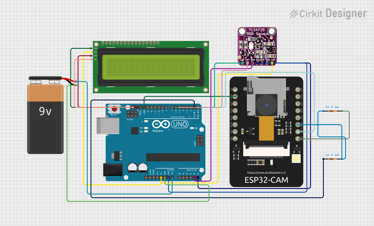
The TCS3472 device provides a digital return of red, green, blue (RGB), and clear light sensing values. An IR blocking filter, integrated on-chip and localized to the color sensing photodiodes, minimizes the IR spectral component of the incoming light and allows color measurements to be made accurately. The high sensitivity, wide dynamic range, and IR blocking filter make the TCS3472 an ideal color sensor solution for use under varying lighting conditions and through attenuating materials.
Explore Projects Built with TCS3472 COLOR LIGHT-TO-DIGITAL CONVERTER with IR FILTER
Explore Projects Built with TCS3472 COLOR LIGHT-TO-DIGITAL CONVERTER with IR FILTER
Common Applications and Use Cases
- Ambient light sensing and color temperature measurement for display backlight control
- Color matching in printing and industrial applications
- Light color temperature measurement for smart lighting systems
- Fluid and gas analysis in medical diagnostics
Technical Specifications
Key Technical Details
- Single 3.3V power supply
- Programmable interrupt function with upper and lower thresholds
- Up to 16-bit color resolution
- I2C fast mode compatible interface
- Temperature range: -30°C to 70°C
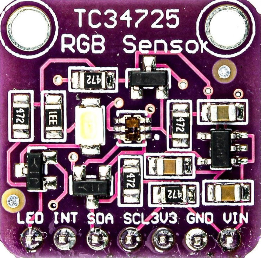
Pin Configuration and Descriptions
| Pin Number | Name | Description |
|---|---|---|
| 1 | VDD | Power supply (2.7V to 3.6V) |
| 2 | GND | Ground reference for power supply |
| 3 | SCL | Serial clock for I2C communication |
| 4 | SDA | Serial data for I2C communication |
| 5 | INT | Interrupt output |
| 6 | LED | Control for external LED |
| 7 | OE | Output enable (active low) |
Usage Instructions
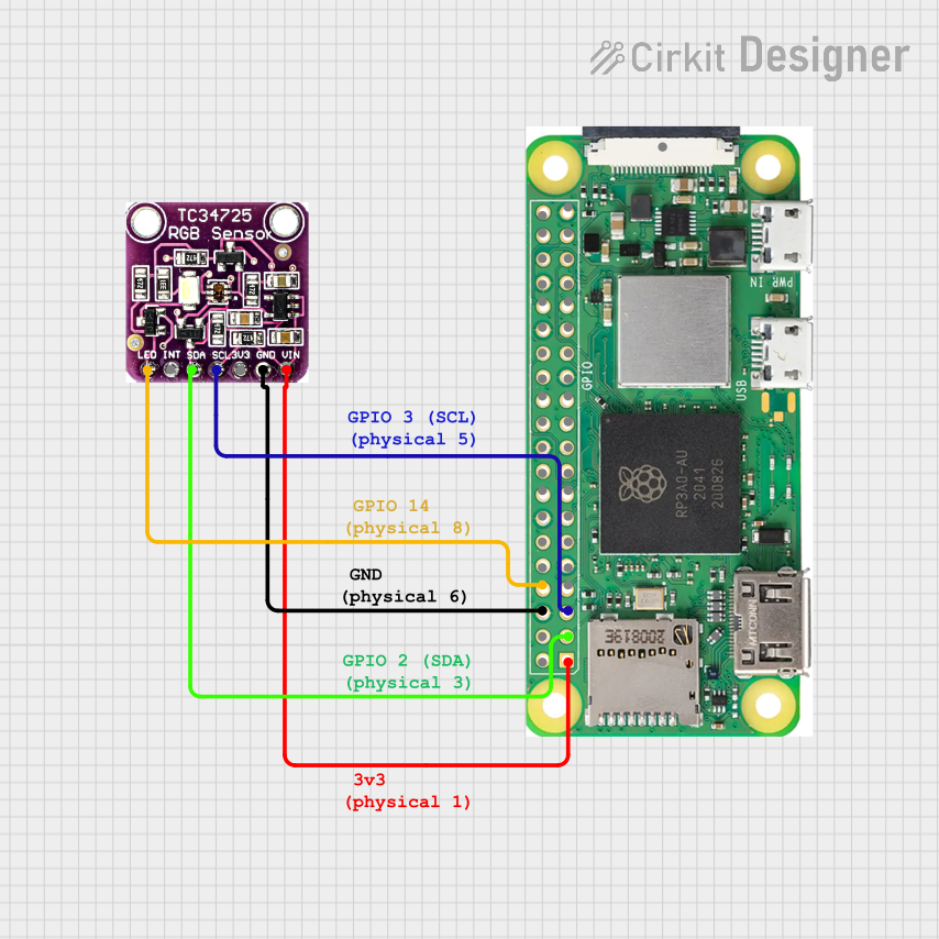
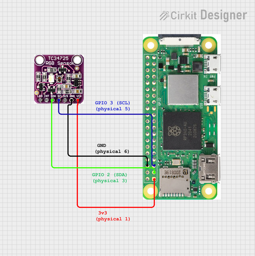
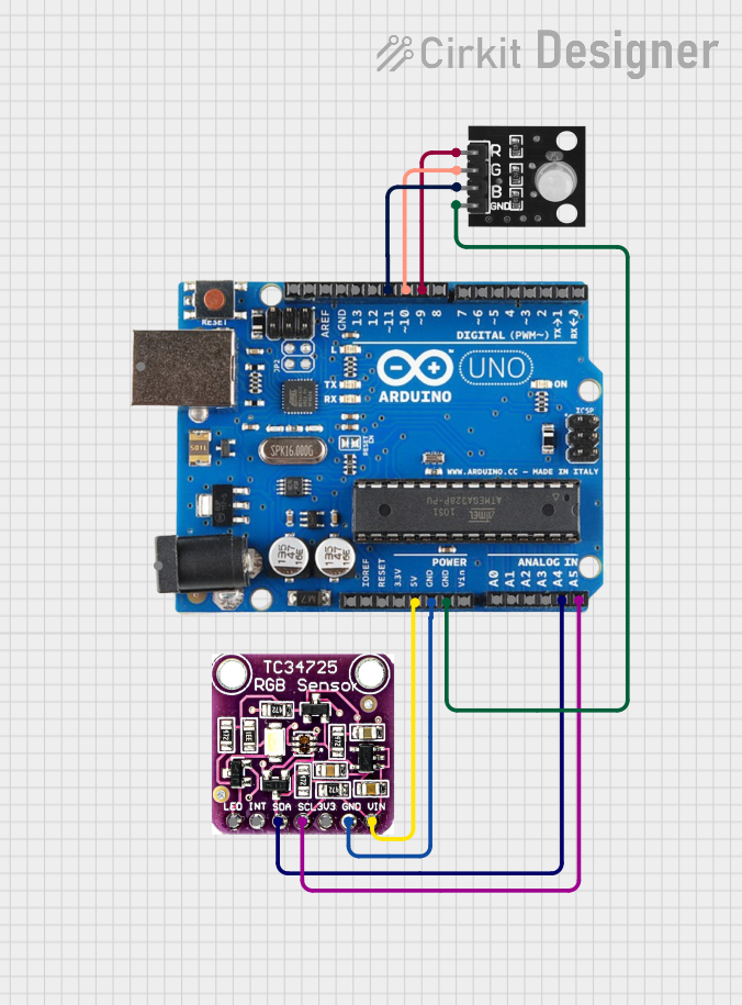
How to Use the Component in a Circuit
- Connect VDD to a 3.3V power supply and GND to the ground.
- Connect SCL and SDA to the I2C clock and data lines, respectively.
- If interrupt functionality is desired, connect the INT pin to a digital input on your microcontroller.
- The OE pin can be left unconnected if not used, or connected to ground to enable the device.
- Optionally, connect an external LED to the LED pin for a controlled light source.
Important Considerations and Best Practices
- Ensure that the power supply is stable and within the specified voltage range.
- Use pull-up resistors on the I2C lines as required by the microcontroller's I2C specification.
- Avoid placing the sensor in direct sunlight or near strong IR sources to prevent saturation.
- Calibrate the sensor for the specific application environment to achieve accurate color measurements.
Example Code for Arduino UNO
#include <Wire.h>
#include "Adafruit_TCS34725.h"

// Create an instance of the TCS34725 sensor
Adafruit_TCS34725 tcs = Adafruit_TCS34725(TCS34725_INTEGRATIONTIME_700MS, TCS34725_GAIN_1X);

void setup() {
  Serial.begin(9600);
  Wire.begin();

  if (tcs.begin()) {
    Serial.println("Found sensor");
  } else {
    Serial.println("No TCS3472 found ... check your connections");
    while (1); // halt!
  }
}

void loop() {
  uint16_t r, g, b, c, colorTemp, lux;

  tcs.getRawData(&r, &g, &b, &c);
  colorTemp = tcs.calculateColorTemperature_dn40(r, g, b, c);
  lux = tcs.calculateLux(r, g, b);

  Serial.print("Color Temp: "); Serial.print(colorTemp, DEC); Serial.print(" K - ");
  Serial.print("Lux: "); Serial.print(lux, DEC); Serial.print(" - ");
  Serial.print("R: "); Serial.print(r, DEC); Serial.print(" ");
  Serial.print("G: "); Serial.print(g, DEC); Serial.print(" ");
  Serial.print("B: "); Serial.print(b, DEC); Serial.print(" ");
  Serial.print("C: "); Serial.print(c, DEC); Serial.println(" ");

  delay(1000);
}
Troubleshooting and FAQs
Common Issues Users Might Face
- Sensor not responding: Ensure that the sensor is correctly powered and that the I2C connections are secure.
- Inaccurate color readings: Verify that the sensor is not exposed to direct sunlight or strong IR sources and that it has been calibrated for the environment.
- Interrupt not triggering: Check the interrupt threshold settings and ensure the INT pin is correctly connected.
Solutions and Tips for Troubleshooting
- Double-check wiring, especially the I2C connections.
- Use the I2C scanner sketch to confirm the sensor's address and connectivity.
- Ensure that the ambient light conditions are consistent with the intended use case when calibrating the sensor.
FAQs
Q: Can the TCS3472 be used with a 5V system? A: The TCS3472 is a 3.3V device, but it can be interfaced with a 5V system using level shifters for the I2C lines.
Q: How can I adjust the integration time and gain?
A: The integration time and gain can be adjusted using the provided library functions, such as tcs.setIntegrationTime() and tcs.setGain().
Q: What is the purpose of the external LED pin? A: The LED pin can be used to drive an external light source, which can be useful for providing consistent lighting conditions for color sensing.
Q: How do I calibrate the sensor for accurate color measurements? A: Calibration involves taking readings under known lighting conditions and adjusting the readings or the environment until the sensor outputs the expected values. This process can be done manually or with the help of calibration software.