How to Use FeedBack Servo: Examples, Pinouts, and Specs
Introduction
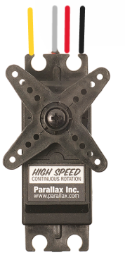
The Parallax Feedback 360° High Speed Servo is an advanced motor control system that combines the functionality of a standard servo with continuous rotation and real-time feedback. This servo is capable of full 360° rotation and provides feedback on the position of the output shaft, making it ideal for precise control in robotics, automation, and interactive art installations.
Explore Projects Built with FeedBack Servo
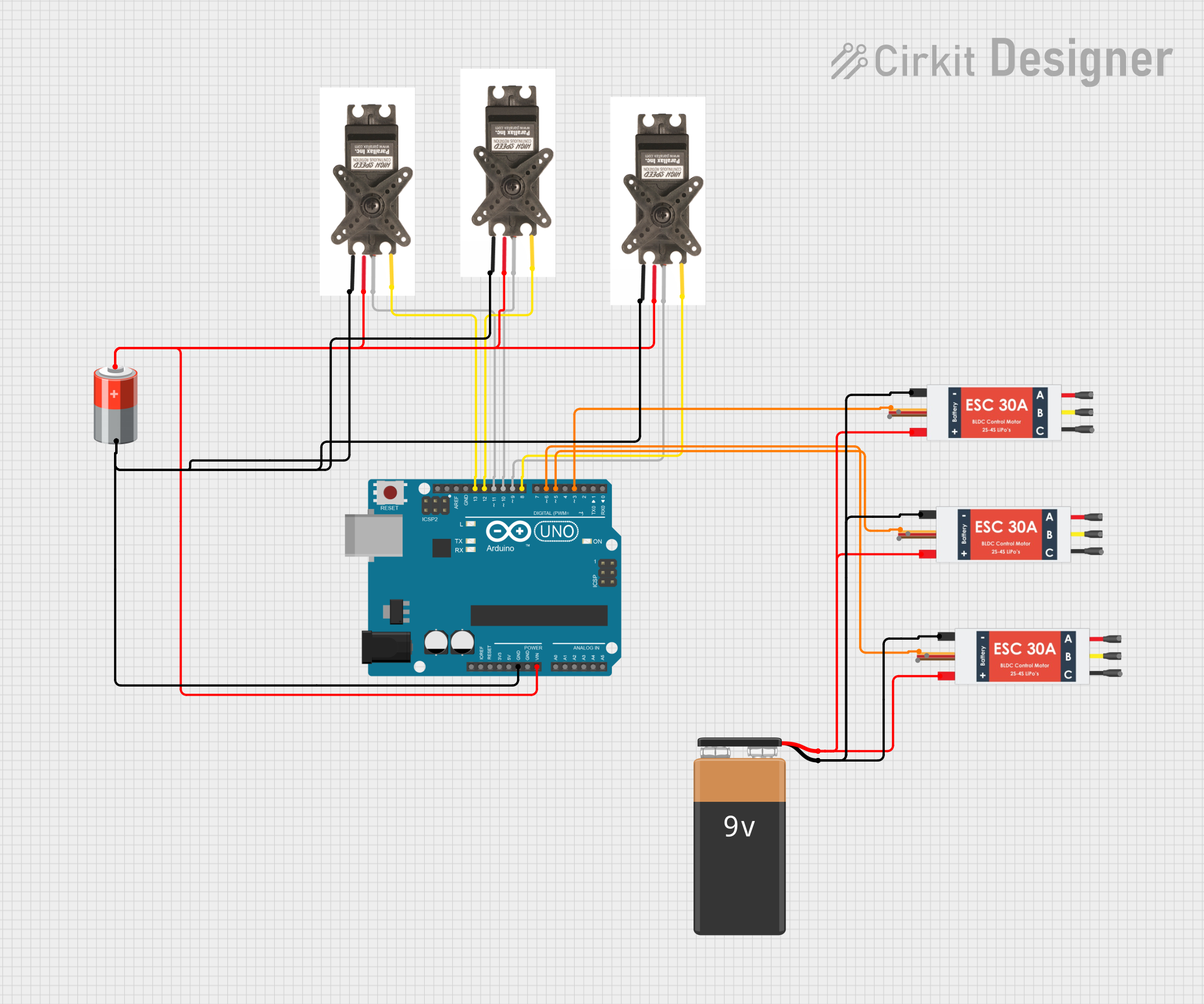

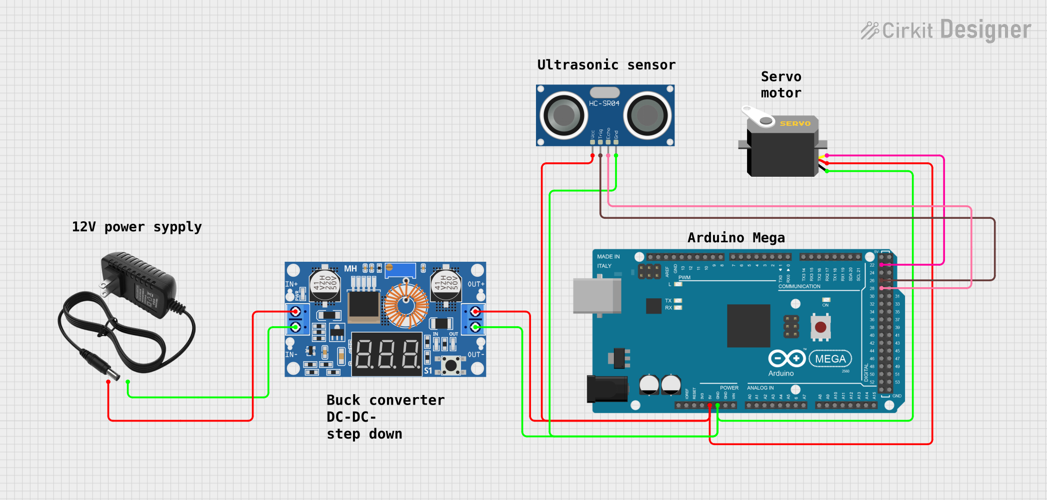
Explore Projects Built with FeedBack Servo
Common Applications and Use Cases
- Robotic arms and grippers
- Automated guided vehicles (AGVs)
- Pan and tilt camera systems
- Interactive exhibits
- Positioning and speed control in conveyor systems
Technical Specifications
Key Technical Details
- Voltage Range: 6.0 to 7.4 VDC
- Maximum Rotation: Continuous
- Speed (6 V): 140 RPM (no load)
- Speed (7.4 V): 160 RPM (no load)
- Stall Torque (6 V): 2.2 kg-cm
- Stall Torque (7.4 V): 2.5 kg-cm
- Feedback Type: Hall effect sensor
Pin Configuration and Descriptions
| Pin Number | Description | Notes |
|---|---|---|
| 1 | Control Signal | PWM input, 3.3-5V tolerant |
| 2 | Power Supply (V+) | 6.0-7.4 VDC |
| 3 | Ground (GND) | Reference ground for power and signal |
| 4 | Feedback | Analog voltage proportional to position |
Usage Instructions
How to Use the Component in a Circuit
- Connect the power supply (V+) to pin 2, ensuring that the voltage is within the specified range.
- Connect the ground (GND) to pin 3.
- Apply a PWM signal to the control signal pin (pin 1) to control the servo's position or speed.
- Read the analog voltage from the feedback pin (pin 4) to determine the position of the servo.
Important Considerations and Best Practices
- Always ensure that the power supply voltage does not exceed the specified maximum to prevent damage to the servo.
- When using the servo for the first time, calibrate the center position by sending a 1.5 ms pulse width modulation (PWM) signal.
- Avoid stalling the servo at high torque for extended periods to prevent overheating and potential damage.
- Use a pull-down or pull-up resistor on the feedback line if noise is present in the feedback signal.
Troubleshooting and FAQs
Common Issues Users Might Face
- Servo not responding: Check the power supply and connections. Ensure the PWM signal is within the correct range.
- Inaccurate positioning: Calibrate the servo's center position and verify the feedback signal.
- Servo jittering: This can be caused by an unstable PWM signal or power supply. Ensure a clean signal and stable voltage.
Solutions and Tips for Troubleshooting
- If the servo is unresponsive, verify the power supply with a multimeter and check the PWM signal with an oscilloscope.
- For calibration issues, use a servo tester or a microcontroller to send precise PWM signals for calibration.
- To reduce jitter, use capacitors to filter the power supply and ensure that the PWM signal is not being affected by electromagnetic interference.
FAQs
Q: Can the servo rotate in both directions?
- A: Yes, the Parallax Feedback 360° High Speed Servo can rotate continuously in both directions.
Q: What is the resolution of the feedback?
- A: The feedback resolution depends on the analog-to-digital converter (ADC) used to read the feedback voltage.
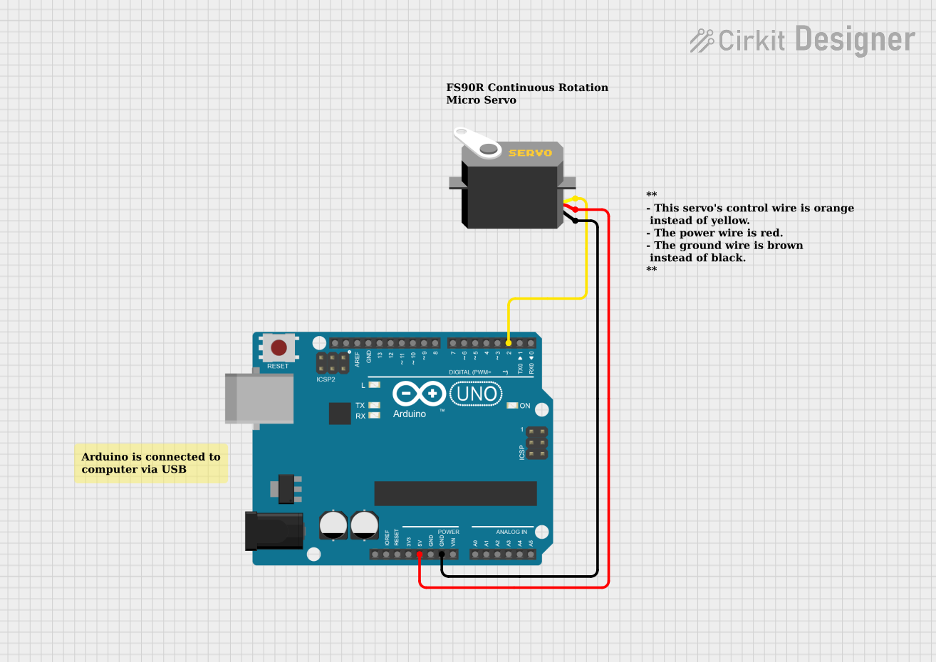
Q: How do I connect this servo to an Arduino UNO?
- A: Connect the servo's power and ground to the Arduino's 5V and GND pins, respectively. Connect the control signal to a PWM-capable pin on the Arduino, and the feedback pin to an analog input.
Example Code for Arduino UNO
#include <Servo.h>

Servo myservo;  // create servo object to control the Parallax servo
int feedbackPin = A0;  // analog pin used to connect the feedback wire
int posFeedback = 0;   // variable to read the value from the analog pin

void setup() {
  myservo.attach(9);  // attaches the servo on pin 9 to the servo object
  Serial.begin(9600); // starts serial communication
}

void loop() {
  int angle = 90; // desired servo position
  // Convert desired angle to PWM pulse width
  int pulseWidth = map(angle, 0, 360, 1280, 1720); // these values may need calibration
  myservo.writeMicroseconds(pulseWidth); // sets the servo position according to the scaled value

  // Reading the feedback from the servo
  posFeedback = analogRead(feedbackPin); // reads the feedback value
  int actualPosition = map(posFeedback, 0, 1023, 0, 360); // scales it to use it with the servo (value between 0 and 360)
  Serial.print("Feedback position: ");
  Serial.println(actualPosition); // prints the position value on the Serial Monitor

  delay(15); // waits for the servo to get there
}
Note: The map function in the example code scales the desired angle to the corresponding PWM pulse width. The actual values may need to be calibrated for your specific servo. The feedback reading is also scaled to represent the position in degrees. The delay function is used to provide time for the servo to reach the desired position. Adjust the delay as necessary for your application.