
How to Use Atmega 16: Examples, Pinouts, and Specs
 Design with Atmega 16 in Cirkit Designer
Introduction
The Atmega 16 is a low-power CMOS 8-bit microcontroller based on the AVR enhanced RISC architecture. It features 16KB of programmable flash memory, 1KB of SRAM, and 512 bytes of EEPROM. This microcontroller is commonly used in embedded systems and robotics due to its versatility and ease of programming. Its robust architecture and ample memory make it suitable for a wide range of applications, from simple control systems to complex automation tasks.
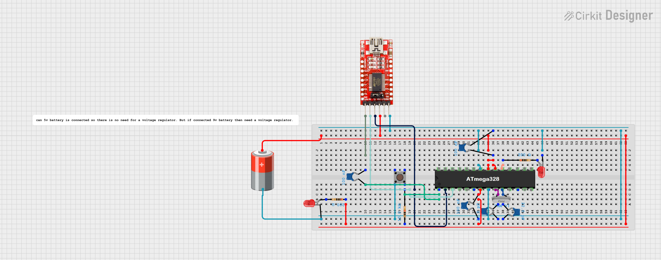
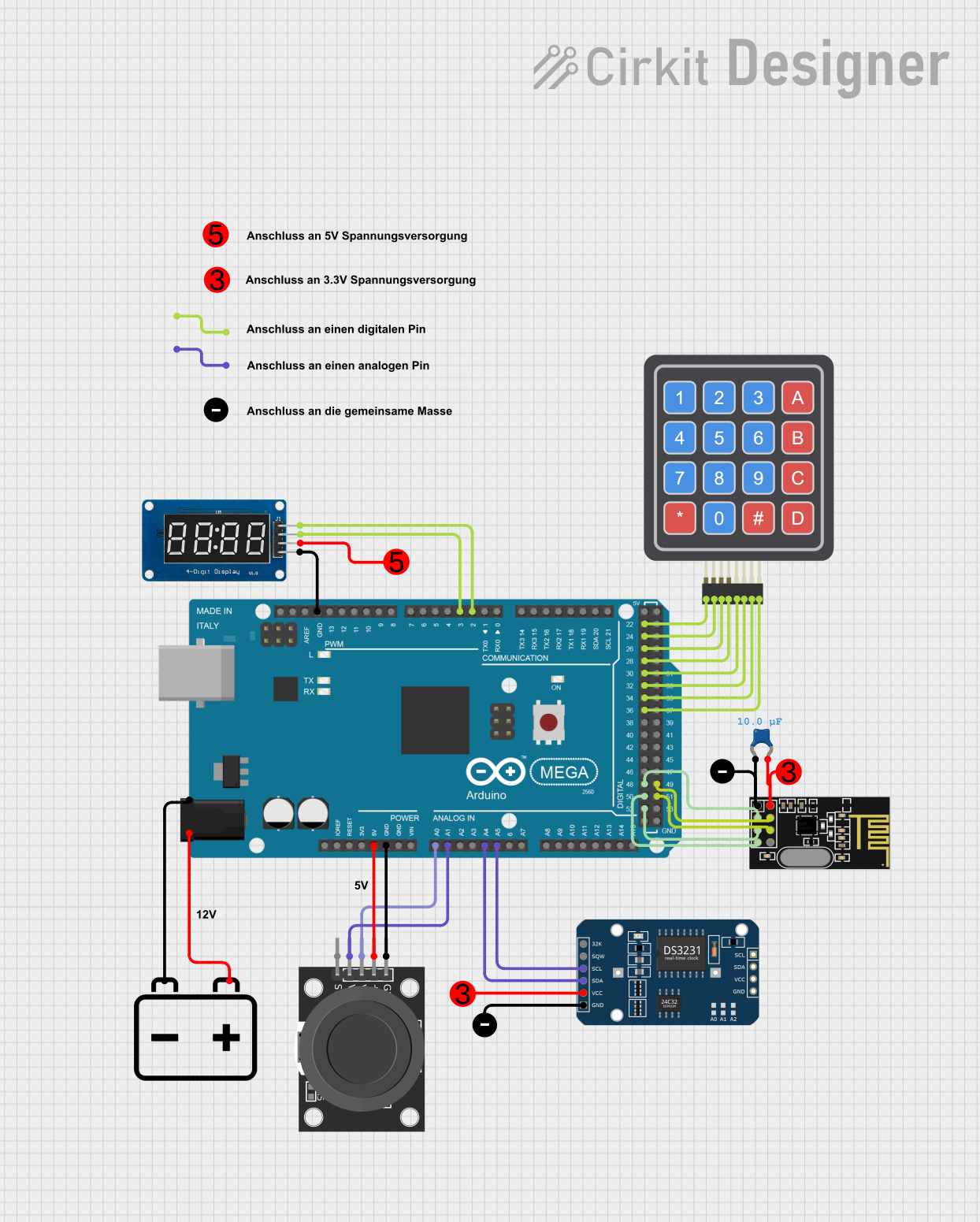
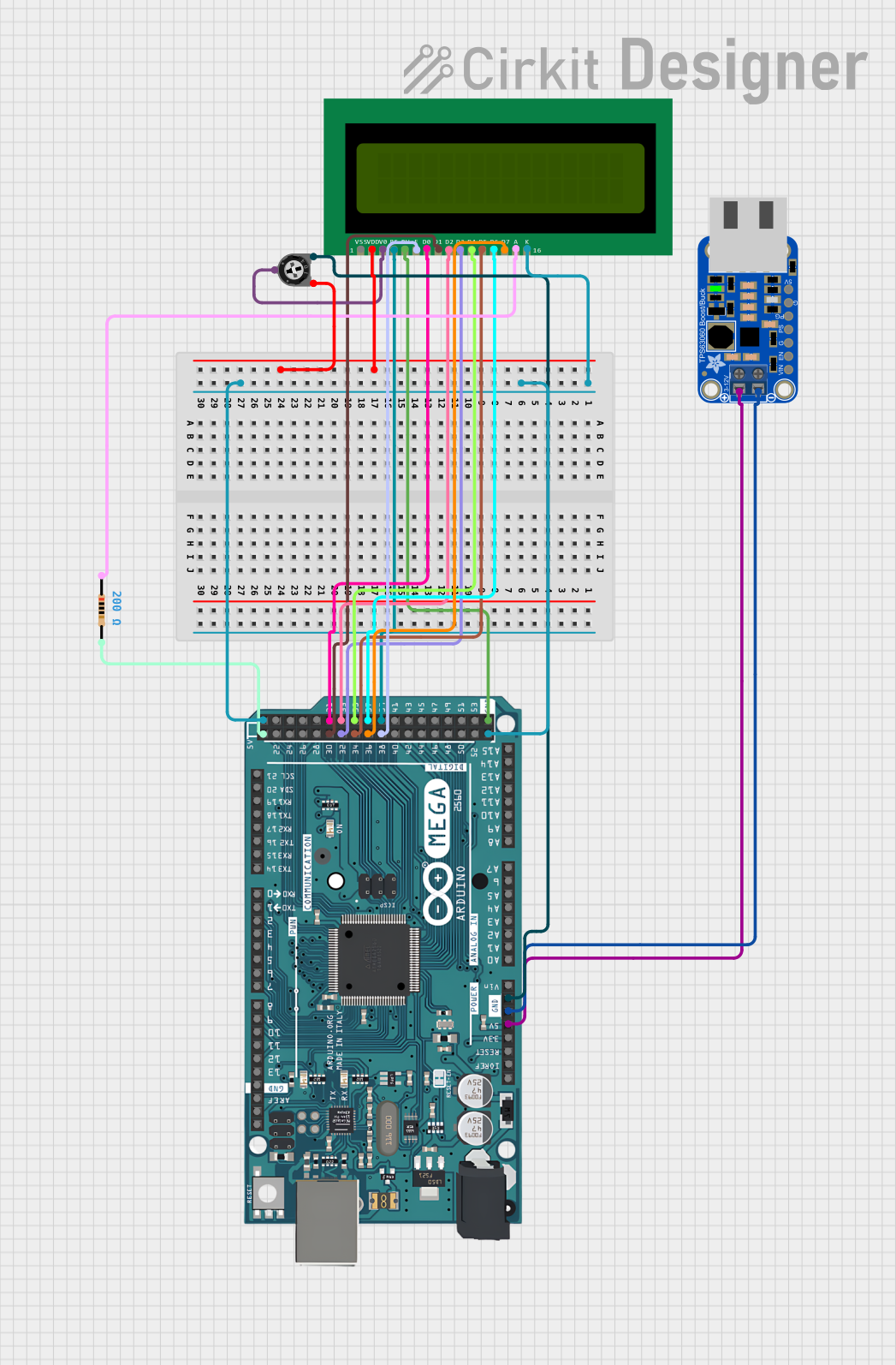
Explore Projects Built with Atmega 16
 Open Project in Cirkit Designer
 Open Project in Cirkit Designer
 Open Project in Cirkit Designer
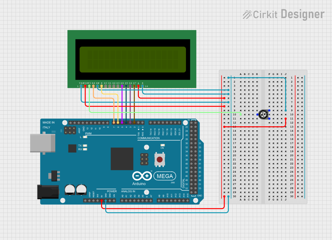
 Open Project in Cirkit Designer
Explore Projects Built with Atmega 16

 Open Project in Cirkit Designer
 Open Project in Cirkit Designer
 Open Project in Cirkit Designer
 Open Project in Cirkit Designer
Technical Specifications
Key Technical Details
| Parameter | Value |
|---|---|
| Architecture | AVR Enhanced RISC |
| Flash Memory | 16KB |
| SRAM | 1KB |
| EEPROM | 512 bytes |
| Operating Voltage | 2.7V - 5.5V |
| Maximum Frequency | 16 MHz |
| I/O Pins | 32 |
| ADC Channels | 8 (10-bit resolution) |
| Timers | 2 x 8-bit, 1 x 16-bit |
| Communication | USART, SPI, I2C |
| Power Consumption | Low power consumption modes |
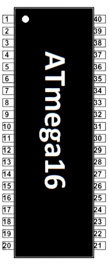
Pin Configuration and Descriptions
| Pin No. | Pin Name | Description |
|---|---|---|
| 1 | PA0 | ADC0/PCINT0 |
| 2 | PA1 | ADC1/PCINT1 |
| 3 | PA2 | ADC2/PCINT2 |
| 4 | PA3 | ADC3/PCINT3 |
| 5 | PA4 | ADC4/PCINT4 |
| 6 | PA5 | ADC5/PCINT5 |
| 7 | PA6 | ADC6/PCINT6 |
| 8 | PA7 | ADC7/PCINT7 |
| 9 | PB0 | XCK/T0/PCINT8 |
| 10 | PB1 | T1/PCINT9 |
| 11 | PB2 | INT2/AIN0/PCINT10 |
| 12 | PB3 | OC0/AIN1/PCINT11 |
| 13 | PB4 | SS/PCINT12 |
| 14 | PB5 | MOSI/PCINT13 |
| 15 | PB6 | MISO/PCINT14 |
| 16 | PB7 | SCK/PCINT15 |
| 17 | RESET | Reset |
| 18 | VCC | Power Supply |
| 19 | GND | Ground |
| 20 | XTAL2 | Crystal Oscillator Pin 2 |
| 21 | XTAL1 | Crystal Oscillator Pin 1 |
| 22 | PD0 | RXD/PCINT16 |
| 23 | PD1 | TXD/PCINT17 |
| 24 | PD2 | INT0/PCINT18 |
| 25 | PD3 | INT1/PCINT19 |
| 26 | PD4 | T0/PCINT20 |
| 27 | PD5 | T1/PCINT21 |
| 28 | PD6 | T2/PCINT22 |
| 29 | PD7 | T3/PCINT23 |
| 30 | PC0 | SCL/PCINT24 |
| 31 | PC1 | SDA/PCINT25 |
| 32 | PC2 | TOSC1/PCINT26 |
| 33 | PC3 | TOSC2/PCINT27 |
| 34 | PC4 | TOSC3/PCINT28 |
| 35 | PC5 | TOSC4/PCINT29 |
| 36 | PC6 | TOSC5/PCINT30 |
| 37 | PC7 | TOSC6/PCINT31 |
| 38 | AVCC | Analog Power Supply |
| 39 | AREF | Analog Reference |
| 40 | GND | Ground |
Usage Instructions
How to Use the Atmega 16 in a Circuit
Power Supply:
- Connect the VCC pin to a 5V power supply.
- Connect the GND pin to the ground of the power supply.
Clock Source:
- Connect a 16 MHz crystal oscillator between XTAL1 and XTAL2 pins.
- Connect two 22pF capacitors from XTAL1 and XTAL2 to ground.
Reset:
- Connect a 10kΩ resistor between the RESET pin and VCC.
- Optionally, connect a push-button between the RESET pin and GND for manual reset.
Programming:
- Use an ISP (In-System Programmer) to program the microcontroller.
- Connect the ISP to the appropriate pins (MISO, MOSI, SCK, RESET, VCC, GND).
I/O Connections:
- Connect sensors, actuators, and other peripherals to the I/O pins as needed.
- Use appropriate pull-up or pull-down resistors for input pins.
Important Considerations and Best Practices
- Decoupling Capacitors: Place 0.1µF decoupling capacitors close to the VCC and AVCC pins to filter out noise.
- Analog Reference: Connect the AREF pin to a stable voltage reference if using the ADC.
- Unused Pins: Configure unused pins as inputs with internal pull-up resistors enabled to reduce power consumption.
- Power Consumption: Utilize sleep modes to reduce power consumption in battery-powered applications.
Troubleshooting and FAQs
Common Issues and Solutions
Microcontroller Not Responding:
- Solution: Check the power supply connections and ensure the correct voltage is applied. Verify the crystal oscillator and reset circuit connections.
Programming Failure:
- Solution: Ensure the ISP connections are correct. Check the programmer settings and ensure the correct microcontroller is selected.
Incorrect ADC Readings:
- Solution: Verify the AREF voltage and ensure it is stable. Check the analog input connections and ensure they are properly connected.
Unexpected Resets:
- Solution: Check for noise on the reset line. Add a capacitor (e.g., 100nF) between the RESET pin and ground to filter out noise.
FAQs
Q1: Can I use the Atmega 16 with an Arduino UNO?
- A1: Yes, you can use the Atmega 16 with an Arduino UNO by configuring the Arduino IDE to support the Atmega 16. You will need an external programmer to upload the code.
Q2: How do I configure the fuses for the Atmega 16?
- A2: Use an AVR programmer and software (e.g., AVRDude) to set the fuses. Refer to the Atmega 16 datasheet for the correct fuse settings.
Q3: Can I use the internal oscillator instead of an external crystal?
- A3: Yes, the Atmega 16 has an internal 8 MHz oscillator. However, for precise timing applications, an external crystal is recommended.
Q4: How do I interface the Atmega 16 with an LCD?
- A4: Connect the data pins of the LCD to the I/O pins of the Atmega 16. Use a library (e.g., LiquidCrystal) to control the LCD.
Example Code for Arduino UNO
// Example code to blink an LED connected to PB0 on Atmega 16

void setup() {
  // Set PB0 as an output pin
  DDRB |= (1 << PB0);
}

void loop() {
  // Turn on the LED
  PORTB |= (1 << PB0);
  delay(1000); // Wait for 1 second

  // Turn off the LED
  PORTB &= ~(1 << PB0);
  delay(1000); // Wait for 1 second
}
This documentation provides a comprehensive guide to using the Atmega 16 microcontroller, covering its technical specifications, usage instructions, and troubleshooting tips. Whether you are a beginner or an experienced user, this guide will help you effectively utilize the Atmega 16 in your projects.