Cirkit Designer Logo
Cirkit Designer
Your all-in-one circuit design IDE
Home / 
Component Documentation

How to Use Q.Station A101T: Examples, Pinouts, and Specs

Image of Q.Station A101T
Cirkit Designer LogoDesign with Q.Station A101T in Cirkit Designer

Introduction

The Q.Station A101T by Gantner Instrument is a compact and versatile signal processing and communication module. Designed for high-performance applications, it excels in environments requiring efficient data acquisition, processing, and communication. Its robust design and advanced features make it suitable for industrial automation, laboratory testing, and IoT-based systems.

Explore Projects Built with Q.Station A101T

Use Cirkit Designer to design, explore, and prototype these projects online. Some projects support real-time simulation. Click "Open Project" to start designing instantly!
Satellite-Based Timing and Navigation System with SDR and Atomic Clock Synchronization
Image of GPS 시스템 측정 구성도_Confirm: A project utilizing Q.Station A101T in a practical application
This circuit appears to be a complex system involving power supply management, GPS and timing synchronization, and data communication. It includes a SI-TEX G1 Satellite Compass for GPS data, an XHTF1021 Atomic Rubidium Clock for precise timing, and Ettus USRP B200 units for software-defined radio communication. Power is supplied through various SMPS units and distributed via terminal blocks and DC jacks. Data communication is facilitated by Beelink MINI S12 N95 computers, RS232 splitters, and a 1000BASE-T Media Converter for network connectivity. RF Directional Couplers are used to interface antennas with the USRP units, and the entire system is likely contained within cases for protection and organization.
Cirkit Designer LogoOpen Project in Cirkit Designer
Satellite Compass and Network-Integrated GPS Data Processing System
Image of GPS 시스템 측정 구성도_241016: A project utilizing Q.Station A101T in a practical application
This circuit comprises a satellite compass, a mini PC, two GPS antennas, power supplies, a network switch, media converters, and an atomic rubidium clock. The satellite compass is powered by a triple output DC power supply and interfaces with an RS232 splitter for 1PPS signals. The mini PCs are connected to the USRP B200 devices via USB for data and power, and to media converters via Ethernet, which in turn connect to a network switch using fiber optic links. The antennas are connected to the USRP B200s through RF directional couplers, and the atomic clock provides a 1PPS input to the RS232 splitter.
Cirkit Designer LogoOpen Project in Cirkit Designer
Battery-Powered GPS Tracker with Bluetooth and APC220 Communication
Image of PANDURTKU0001_basic: A project utilizing Q.Station A101T in a practical application
This circuit integrates a SparkFun Qwiic GPS-RTK2 module with an APC220 radio module and an HC-05 Bluetooth module to provide GPS data transmission via both radio and Bluetooth. The circuit is powered by a 5V battery and includes switches to control power to the GPS module and the APC220 module, with an embedded GPS antenna for signal reception.
Cirkit Designer LogoOpen Project in Cirkit Designer
Solar-Powered GSM/GPRS+GPS Tracker with Seeeduino XIAO
Image of SOS System : A project utilizing Q.Station A101T in a practical application
This circuit features an Ai Thinker A9G development board for GSM/GPRS and GPS/BDS connectivity, interfaced with a Seeeduino XIAO microcontroller for control and data processing. A solar cell, coupled with a TP4056 charging module, charges a 3.3V battery, which powers the system through a 3.3V regulator ensuring stable operation. The circuit likely serves for remote data communication and location tracking, with the capability to be powered by renewable energy and interfaced with additional sensors or input devices via the Seeeduino XIAO.
Cirkit Designer LogoOpen Project in Cirkit Designer

Explore Projects Built with Q.Station A101T

Use Cirkit Designer to design, explore, and prototype these projects online. Some projects support real-time simulation. Click "Open Project" to start designing instantly!
Image of GPS 시스템 측정 구성도_Confirm: A project utilizing Q.Station A101T in a practical application
Satellite-Based Timing and Navigation System with SDR and Atomic Clock Synchronization
This circuit appears to be a complex system involving power supply management, GPS and timing synchronization, and data communication. It includes a SI-TEX G1 Satellite Compass for GPS data, an XHTF1021 Atomic Rubidium Clock for precise timing, and Ettus USRP B200 units for software-defined radio communication. Power is supplied through various SMPS units and distributed via terminal blocks and DC jacks. Data communication is facilitated by Beelink MINI S12 N95 computers, RS232 splitters, and a 1000BASE-T Media Converter for network connectivity. RF Directional Couplers are used to interface antennas with the USRP units, and the entire system is likely contained within cases for protection and organization.
Cirkit Designer LogoOpen Project in Cirkit Designer
Image of GPS 시스템 측정 구성도_241016: A project utilizing Q.Station A101T in a practical application
Satellite Compass and Network-Integrated GPS Data Processing System
This circuit comprises a satellite compass, a mini PC, two GPS antennas, power supplies, a network switch, media converters, and an atomic rubidium clock. The satellite compass is powered by a triple output DC power supply and interfaces with an RS232 splitter for 1PPS signals. The mini PCs are connected to the USRP B200 devices via USB for data and power, and to media converters via Ethernet, which in turn connect to a network switch using fiber optic links. The antennas are connected to the USRP B200s through RF directional couplers, and the atomic clock provides a 1PPS input to the RS232 splitter.
Cirkit Designer LogoOpen Project in Cirkit Designer
Image of PANDURTKU0001_basic: A project utilizing Q.Station A101T in a practical application
Battery-Powered GPS Tracker with Bluetooth and APC220 Communication
This circuit integrates a SparkFun Qwiic GPS-RTK2 module with an APC220 radio module and an HC-05 Bluetooth module to provide GPS data transmission via both radio and Bluetooth. The circuit is powered by a 5V battery and includes switches to control power to the GPS module and the APC220 module, with an embedded GPS antenna for signal reception.
Cirkit Designer LogoOpen Project in Cirkit Designer
Image of SOS System : A project utilizing Q.Station A101T in a practical application
Solar-Powered GSM/GPRS+GPS Tracker with Seeeduino XIAO
This circuit features an Ai Thinker A9G development board for GSM/GPRS and GPS/BDS connectivity, interfaced with a Seeeduino XIAO microcontroller for control and data processing. A solar cell, coupled with a TP4056 charging module, charges a 3.3V battery, which powers the system through a 3.3V regulator ensuring stable operation. The circuit likely serves for remote data communication and location tracking, with the capability to be powered by renewable energy and interfaced with additional sensors or input devices via the Seeeduino XIAO.
Cirkit Designer LogoOpen Project in Cirkit Designer

Common Applications and Use Cases

  • Industrial automation and control systems
  • Data acquisition in laboratory environments
  • IoT-based monitoring and communication
  • Signal processing for sensors and actuators
  • Distributed control systems in manufacturing

Technical Specifications

Key Technical Details

Parameter Specification
Manufacturer Part ID Q.Station A101T
Power Supply Voltage 9–36 V DC
Power Consumption < 5 W
Communication Interfaces Ethernet, RS485, CAN
Signal Processing Rate Up to 100 kHz
Operating Temperature -20°C to +60°C
Dimensions 120 mm x 75 mm x 30 mm
Weight 250 g
Mounting Options DIN rail or panel mounting

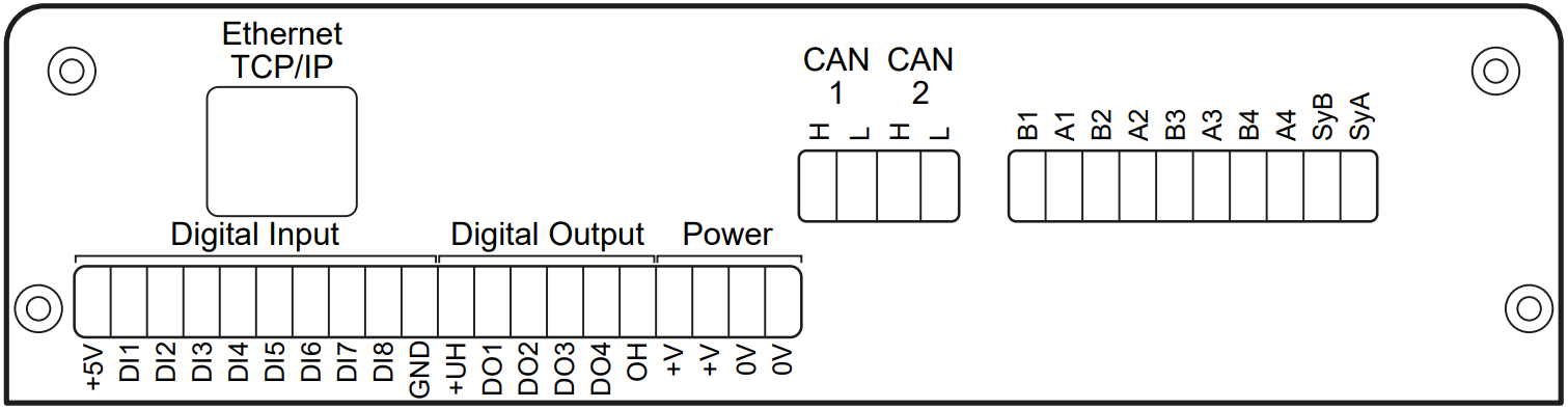
Pin Configuration and Descriptions

The Q.Station A101T features multiple connectors for power, communication, and signal input/output. Below is the pin configuration for the primary connectors:

Power Connector

Pin Number Description
1 +V (9–36 V DC)
2 Ground (GND)

Ethernet Port (RJ45)

Pin Number Description
1 TX+ (Transmit +)
2 TX- (Transmit -)
3 RX+ (Receive +)
4 Not Connected
5 Not Connected
6 RX- (Receive -)
7 Not Connected
8 Not Connected

RS485 Connector

Pin Number Description
1 A (Data +)
2 B (Data -)
3 Ground (GND)

CAN Bus Connector

Pin Number Description
1 CAN High (CAN_H)
2 CAN Low (CAN_L)
3 Ground (GND)

Usage Instructions

How to Use the Q.Station A101T in a Circuit

  1. Power Connection: Connect the power supply to the power connector, ensuring the voltage is within the 9–36 V DC range.
  2. Communication Setup:
    • For Ethernet communication, connect the RJ45 port to your network.
    • For RS485 or CAN communication, wire the respective connectors to your system.
  3. Signal Input/Output: Connect sensors, actuators, or other devices to the appropriate signal input/output ports.
  4. Configuration: Use the provided software or web interface to configure the Q.Station A101T for your specific application.
  5. Data Acquisition: Start acquiring and processing data as per your system requirements.

Important Considerations and Best Practices

  • Ensure the power supply voltage is stable and within the specified range to avoid damage.
  • Use shielded cables for communication interfaces to minimize noise and interference.
  • Mount the Q.Station A101T securely on a DIN rail or panel to prevent vibration-related issues.
  • Regularly update the firmware to access the latest features and improvements.
  • For Ethernet communication, assign a static IP address to avoid network conflicts.

Example: Connecting to an Arduino UNO

The Q.Station A101T can communicate with an Arduino UNO via RS485. Below is an example Arduino sketch for basic communication:

#include <SoftwareSerial.h>

// Define RS485 pins for Arduino
#define RX_PIN 10  // Arduino pin connected to RS485 A (Data +)
#define TX_PIN 11  // Arduino pin connected to RS485 B (Data -)

// Initialize SoftwareSerial for RS485 communication
SoftwareSerial rs485(RX_PIN, TX_PIN);

void setup() {
  // Start serial communication for debugging
  Serial.begin(9600);
  // Start RS485 communication
  rs485.begin(9600);
  Serial.println("RS485 communication initialized.");
}

void loop() {
  // Send data to Q.Station A101T
  rs485.println("Hello, Q.Station A101T!");
  Serial.println("Message sent to Q.Station A101T.");

  // Wait for a response
  if (rs485.available()) {
    String response = rs485.readString();
    Serial.print("Response from Q.Station A101T: ");
    Serial.println(response);
  }

  delay(1000); // Wait 1 second before sending the next message
}

Notes:

  • Use an RS485-to-TTL converter module to interface the Arduino UNO with the Q.Station A101T.
  • Ensure proper termination resistors are used on the RS485 bus to maintain signal integrity.

Troubleshooting and FAQs

Common Issues and Solutions

  1. No Power to the Device

    • Cause: Incorrect power supply voltage or loose connections.
    • Solution: Verify the power supply voltage is within the 9–36 V DC range and check all connections.
  2. Communication Failure

    • Cause: Incorrect wiring or configuration.
    • Solution: Double-check the wiring and ensure the communication settings (e.g., baud rate) match between devices.
  3. Data Loss or Noise

    • Cause: Electromagnetic interference or improper grounding.
    • Solution: Use shielded cables and ensure proper grounding of the system.
  4. Device Overheating

    • Cause: Operating outside the specified temperature range.
    • Solution: Ensure the device is used within the -20°C to +60°C range and has adequate ventilation.

FAQs

  1. Can the Q.Station A101T be used in outdoor environments?

    • Yes, but it must be housed in a weatherproof enclosure to protect it from moisture and dust.
  2. What is the maximum cable length for RS485 communication?

    • The maximum recommended cable length is 1200 meters, depending on the baud rate and cable quality.
  3. Does the Q.Station A101T support wireless communication?

    • No, the Q.Station A101T does not have built-in wireless capabilities. However, it can be connected to a wireless router or gateway for wireless communication.
  4. How do I update the firmware?

    • Firmware updates can be performed via the Ethernet interface using the manufacturer's software or web interface.

By following this documentation, users can effectively integrate and operate the Q.Station A101T in their electronic systems.