How to Use Led 7 đoạn 6 số: Examples, Pinouts, and Specs
Introduction
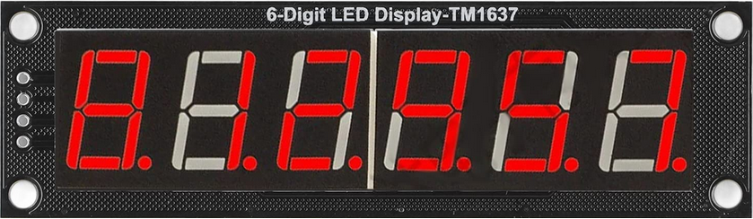
The LED 7-Đoạn 6-Số (Manufacturer Part ID: led7doan6so) is a 7-segment LED display module with six digits, designed for visually representing numerical information. Each digit consists of seven individual LED segments arranged in a figure-eight pattern, with an additional decimal point for precision-based applications. This component is widely used in digital clocks, counters, calculators, and other devices requiring numerical displays.
Manufactured in China, this display is compact, efficient, and easy to integrate into various electronic circuits, making it a popular choice for hobbyists and professionals alike.
Explore Projects Built with Led 7 đoạn 6 số
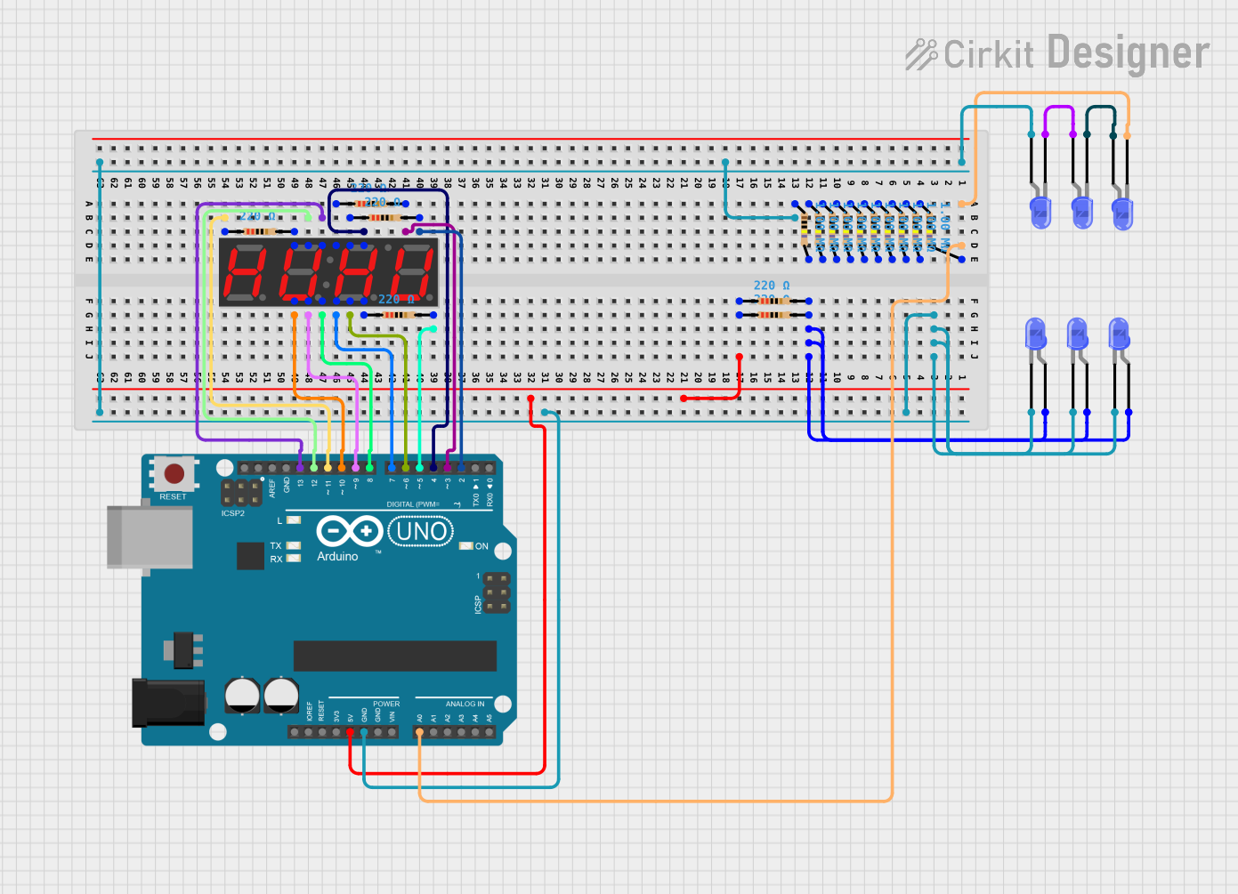

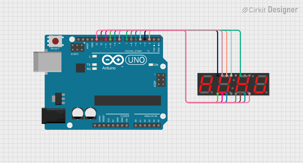
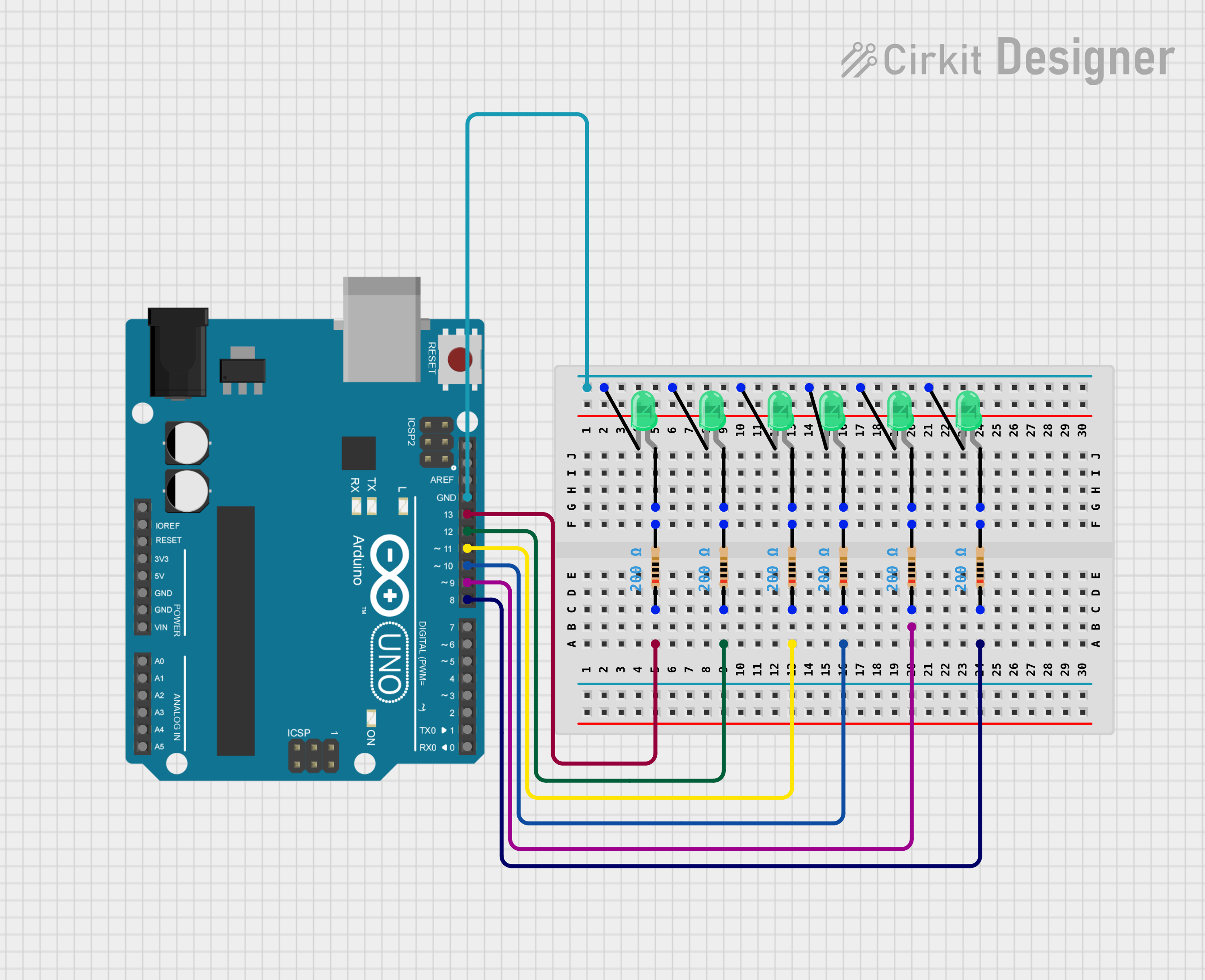
Explore Projects Built with Led 7 đoạn 6 số
Common Applications
- Digital clocks and timers
- Electronic counters
- Temperature and voltage displays
- Arduino-based projects
- Industrial control panels
Technical Specifications
Key Technical Details
| Parameter | Specification |
|---|---|
| Manufacturer | China |
| Part ID | led7doan6so |
| Number of Digits | 6 |
| Segment Type | Common Cathode or Common Anode* |
| Operating Voltage | 2.0V - 3.3V (per segment) |
| Forward Current | 10mA - 20mA (per segment) |
| Peak Forward Current | 100mA (per segment, <10ms pulse) |
| Power Dissipation | 80mW (per segment) |
| Operating Temperature | -40°C to +85°C |
| Dimensions | Varies by model (e.g., 75mm x 15mm) |
*Note: Ensure you verify whether your specific module is common cathode or common anode before use.
Pin Configuration and Descriptions
The LED 7-Đoạn 6-Số module typically has 12 to 16 pins, depending on the specific design. Below is a general pinout for a common cathode configuration:
| Pin Number | Description |
|---|---|
| 1 | Digit 1 Cathode (or Anode) |
| 2 | Segment A |
| 3 | Segment B |
| 4 | Digit 2 Cathode (or Anode) |
| 5 | Segment C |
| 6 | Segment D |
| 7 | Digit 3 Cathode (or Anode) |
| 8 | Segment E |
| 9 | Segment F |
| 10 | Digit 4 Cathode (or Anode) |
| 11 | Segment G |
| 12 | Decimal Point |
| 13 | Digit 5 Cathode (or Anode) |
| 14 | Digit 6 Cathode (or Anode) |
Note: Pin configurations may vary slightly depending on the manufacturer. Always refer to the datasheet for your specific module.
Usage Instructions
How to Use the Component in a Circuit
- Determine the Configuration: Identify whether your module is common cathode or common anode. This will affect how you connect the power supply and control signals.
- Connect Power:
- For a common cathode display, connect all cathode pins to ground.
- For a common anode display, connect all anode pins to the positive voltage supply.
- Control Segments: Use current-limiting resistors (typically 220Ω to 1kΩ) to connect each segment pin to a microcontroller or driver circuit. This prevents excessive current from damaging the LEDs.
- Multiplexing: To control all six digits with fewer pins, use a multiplexing technique. Activate one digit at a time while controlling the corresponding segments.
- Microcontroller Integration: Connect the segment and digit pins to GPIO pins on a microcontroller (e.g., Arduino UNO). Use software to control which segments light up.
Important Considerations and Best Practices
- Current Limiting: Always use resistors to limit current through the segments.
- Brightness Control: Adjust the resistor values or use PWM (Pulse Width Modulation) to control brightness.
- Power Supply: Ensure your power supply can handle the total current draw of all active segments.
- Heat Management: Avoid prolonged operation at maximum current to prevent overheating.
Example: Arduino UNO Code
Below is an example of how to control a single digit of the LED 7-Đoạn 6-Số display using an Arduino UNO:
// Define segment pins (common cathode example)
const int segmentPins[] = {2, 3, 4, 5, 6, 7, 8}; // A, B, C, D, E, F, G
const int digitPin = 9; // Common cathode pin for the digit

// Segment patterns for numbers 0-9
const byte digitPatterns[] = {
  0b00111111, // 0
  0b00000110, // 1
  0b01011011, // 2
  0b01001111, // 3
  0b01100110, // 4
  0b01101101, // 5
  0b01111101, // 6
  0b00000111, // 7
  0b01111111, // 8
  0b01101111  // 9
};

void setup() {
  // Set segment pins as outputs
  for (int i = 0; i < 7; i++) {
    pinMode(segmentPins[i], OUTPUT);
  }
  pinMode(digitPin, OUTPUT);
}

void loop() {
  // Display the number 5
  displayDigit(5);
  delay(1000); // Wait for 1 second
}

void displayDigit(int number) {
  // Activate the digit
  digitalWrite(digitPin, LOW); // LOW for common cathode, HIGH for common anode

  // Set segment states
  for (int i = 0; i < 7; i++) {
    digitalWrite(segmentPins[i], (digitPatterns[number] >> i) & 0x01);
  }
}
Troubleshooting and FAQs
Common Issues
Segments Not Lighting Up:
- Check the connections and ensure all pins are properly connected.
- Verify that the current-limiting resistors are not too high.
- Ensure the power supply voltage matches the module's requirements.
Incorrect Digits Displayed:
- Double-check the wiring of segment pins to the microcontroller.
- Verify the software logic for segment control.
Dim Display:
- Reduce the value of the current-limiting resistors (but do not exceed the maximum current rating).
- Ensure the power supply can provide sufficient current.
Overheating:
- Check for excessive current through the segments.
- Use proper resistors and avoid prolonged operation at maximum brightness.
FAQs
Q: Can I control this display with fewer pins?
A: Yes, you can use a shift register (e.g., 74HC595) or a dedicated LED driver IC (e.g., MAX7219) to reduce the number of GPIO pins required.
Q: How do I know if my display is common cathode or common anode?
A: Refer to the datasheet or test the module by connecting a single segment to power and ground. Observe which configuration lights up the segment.
Q: Can I use this display with a 3.3V microcontroller?
A: Yes, but ensure the forward voltage of the LEDs is compatible, and adjust resistor values accordingly.
This documentation provides a comprehensive guide to using the LED 7-Đoạn 6-Số module effectively. For further assistance, consult the manufacturer's datasheet or community forums.