Cirkit Designer Logo
Cirkit Designer
Your all-in-one circuit design IDE
Home / 
Component Documentation

How to Use Switching Power Supply: Examples, Pinouts, and Specs

Image of Switching Power Supply
Cirkit Designer LogoDesign with Switching Power Supply in Cirkit Designer

Introduction

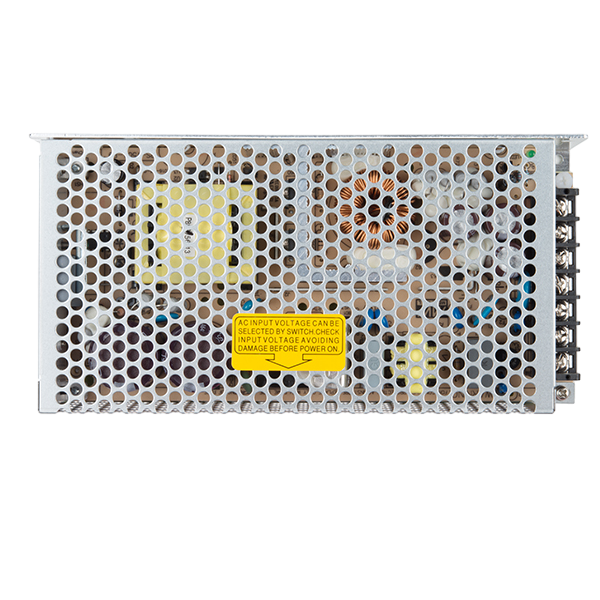
The Mean Well 12V DC Switching Power Supply is a highly efficient device designed to convert electrical power using a switching regulator. This component ensures a stable 12V DC output, making it ideal for a wide range of applications. Switching power supplies are commonly used in various electronic devices, including computers, industrial equipment, and consumer electronics, due to their efficiency and reliability.

Explore Projects Built with Switching Power Supply

Use Cirkit Designer to design, explore, and prototype these projects online. Some projects support real-time simulation. Click "Open Project" to start designing instantly!
AC to DC Power Supply with Transformer and Bridge Rectifier
Image of BRIDGE RECTIFIER: A project utilizing Switching Power Supply in a practical application
This circuit is a basic AC to DC power supply that steps down 220V AC to a lower voltage using a transformer, rectifies it to DC using a bridge rectifier made of diodes, and smooths the output with an electrolytic capacitor. A rocker switch is used to turn the power supply on and off.
Cirkit Designer LogoOpen Project in Cirkit Designer
12V UPS System with Dual 18650 Li-ion Battery Backup and Voltage Regulation
Image of Power supply: A project utilizing Switching Power Supply in a practical application
This circuit is designed to provide an uninterruptible power supply (UPS) system with a 12V DC output. It includes a 12V 5A power supply connected to an AC source through a toggle switch, which charges a pair of 18650 Li-ion batteries via a voltage regulator (XL4016). The UPS module ensures a continuous power supply to the load by switching between the power supply and the battery bank.
Cirkit Designer LogoOpen Project in Cirkit Designer
Battery-Powered UPS with Step-Down Buck Converter and BMS
Image of Mini ups: A project utilizing Switching Power Supply in a practical application
This circuit is a power management system that steps down a 240V AC input to a lower DC voltage using a buck converter, which then powers a 40W UPS. The UPS is controlled by a rocker switch and is backed up by a battery management system (BMS) connected to three 3.7V batteries in series, ensuring continuous power supply.
Cirkit Designer LogoOpen Project in Cirkit Designer
Dual 5V Power Supply Distribution Circuit with Toggle Switch Control
Image of rfdriver: A project utilizing Switching Power Supply in a practical application
This circuit consists of two 5V 5A power supplies connected to an AC wall plug point, providing DC output through a 12-way connector. The ground connections from both power supplies are interconnected and also connected to the ground pins of two toggle switches. The DC outputs from the power supplies are separately connected to different pins on the 12-way connector, with each power supply output being switchable via one of the toggle switches.
Cirkit Designer LogoOpen Project in Cirkit Designer

Explore Projects Built with Switching Power Supply

Use Cirkit Designer to design, explore, and prototype these projects online. Some projects support real-time simulation. Click "Open Project" to start designing instantly!
Image of BRIDGE RECTIFIER: A project utilizing Switching Power Supply in a practical application
AC to DC Power Supply with Transformer and Bridge Rectifier
This circuit is a basic AC to DC power supply that steps down 220V AC to a lower voltage using a transformer, rectifies it to DC using a bridge rectifier made of diodes, and smooths the output with an electrolytic capacitor. A rocker switch is used to turn the power supply on and off.
Cirkit Designer LogoOpen Project in Cirkit Designer
Image of Power supply: A project utilizing Switching Power Supply in a practical application
12V UPS System with Dual 18650 Li-ion Battery Backup and Voltage Regulation
This circuit is designed to provide an uninterruptible power supply (UPS) system with a 12V DC output. It includes a 12V 5A power supply connected to an AC source through a toggle switch, which charges a pair of 18650 Li-ion batteries via a voltage regulator (XL4016). The UPS module ensures a continuous power supply to the load by switching between the power supply and the battery bank.
Cirkit Designer LogoOpen Project in Cirkit Designer
Image of Mini ups: A project utilizing Switching Power Supply in a practical application
Battery-Powered UPS with Step-Down Buck Converter and BMS
This circuit is a power management system that steps down a 240V AC input to a lower DC voltage using a buck converter, which then powers a 40W UPS. The UPS is controlled by a rocker switch and is backed up by a battery management system (BMS) connected to three 3.7V batteries in series, ensuring continuous power supply.
Cirkit Designer LogoOpen Project in Cirkit Designer
Image of rfdriver: A project utilizing Switching Power Supply in a practical application
Dual 5V Power Supply Distribution Circuit with Toggle Switch Control
This circuit consists of two 5V 5A power supplies connected to an AC wall plug point, providing DC output through a 12-way connector. The ground connections from both power supplies are interconnected and also connected to the ground pins of two toggle switches. The DC outputs from the power supplies are separately connected to different pins on the 12-way connector, with each power supply output being switchable via one of the toggle switches.
Cirkit Designer LogoOpen Project in Cirkit Designer

Technical Specifications

Below are the key technical details and pin configuration for the Mean Well 12V DC Switching Power Supply:

Key Technical Details

Parameter Value
Input Voltage Range 85-264V AC / 120-370V DC
Output Voltage 12V DC
Output Current 0-10A
Power Rating 120W
Efficiency Up to 90%
Operating Temperature -20°C to +70°C
Dimensions 159 x 97 x 38 mm
Weight 0.6 kg

Pin Configuration and Descriptions

Pin No. Name Description
1 AC-L AC Live Input
2 AC-N AC Neutral Input
3 FG Frame Ground
4 +V Positive DC Output
5 -V Negative DC Output
6 ADJ Output Voltage Adjustment (±10%)

Usage Instructions

How to Use the Component in a Circuit

  1. Power Connection:

    • Connect the AC-L pin to the live wire of the AC power source.
    • Connect the AC-N pin to the neutral wire of the AC power source.
    • Connect the FG pin to the ground for safety.
  2. Output Connection:

    • Connect the +V pin to the positive terminal of your load.
    • Connect the -V pin to the negative terminal of your load.
  3. Voltage Adjustment:

    • Use the ADJ pin to fine-tune the output voltage within ±10% of the nominal 12V.

Important Considerations and Best Practices

  • Heat Dissipation: Ensure adequate ventilation around the power supply to prevent overheating.
  • Load Requirements: Verify that the load does not exceed the maximum output current of 10A.
  • Safety Precautions: Always disconnect the power supply from the mains before making any connections or adjustments.
  • Grounding: Properly ground the FG pin to avoid electrical hazards.

Troubleshooting and FAQs

Common Issues and Solutions

  1. No Output Voltage:

    • Check Connections: Ensure all input and output connections are secure.
    • Verify Input Voltage: Confirm that the input voltage is within the specified range.
    • Overload Protection: Reduce the load to ensure it does not exceed the maximum current rating.
  2. Overheating:

    • Ventilation: Ensure the power supply has adequate ventilation.
    • Ambient Temperature: Check that the operating environment is within the specified temperature range.
  3. Output Voltage Fluctuations:

    • Load Stability: Ensure the load is stable and does not have sudden large variations.
    • Voltage Adjustment: Use the ADJ pin to fine-tune the output voltage.

FAQs

Q1: Can I use this power supply with an Arduino UNO?

  • A1: Yes, you can use this power supply to provide a stable 12V DC to your Arduino UNO. However, ensure that you use a voltage regulator or a step-down converter to bring the voltage down to 5V or 7-12V for the Arduino's input.

Q2: How do I adjust the output voltage?

  • A2: Use a small screwdriver to turn the potentiometer connected to the ADJ pin. Turning it clockwise will increase the voltage, while turning it counterclockwise will decrease it.

Q3: What should I do if the power supply is not working?

  • A3: Check all connections, verify the input voltage, and ensure the load does not exceed the maximum current rating. If the issue persists, consult the manufacturer’s support.

Example Code for Arduino UNO

Here is an example of how to connect the Mean Well 12V DC Switching Power Supply to an Arduino UNO using a step-down converter to provide a stable 5V input:

// Example code to blink an LED connected to Arduino UNO
// Ensure the power supply is connected to a step-down converter
// to provide 5V to the Arduino's 5V pin.

const int ledPin = 13; // Pin number for the LED

void setup() {
  pinMode(ledPin, OUTPUT); // Set the LED pin as an output
}

void loop() {
  digitalWrite(ledPin, HIGH); // Turn the LED on
  delay(1000); // Wait for 1 second
  digitalWrite(ledPin, LOW); // Turn the LED off
  delay(1000); // Wait for 1 second
}

Ensure that the step-down converter is properly connected to the 12V output of the power supply and the 5V input of the Arduino UNO.


This documentation provides a comprehensive guide to using the Mean Well 12V DC Switching Power Supply, covering technical specifications, usage instructions, troubleshooting tips, and example code for integration with an Arduino UNO.