How to Use OpenCrBoard: Examples, Pinouts, and Specs
Introduction
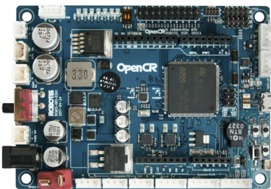
The OpenCrBoard is a versatile microcontroller board specifically designed for robotics and IoT (Internet of Things) applications. It offers a wide range of connectivity options, including Bluetooth and Wi-Fi, and is compatible with various sensors and actuators. This makes it an excellent choice for educational, hobbyist, and prototyping projects. The board is engineered to simplify the development of robotic systems and IoT devices, providing robust performance and flexibility.
Explore Projects Built with OpenCrBoard

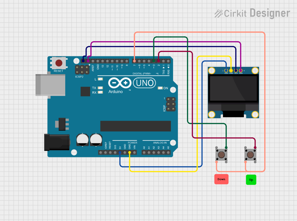

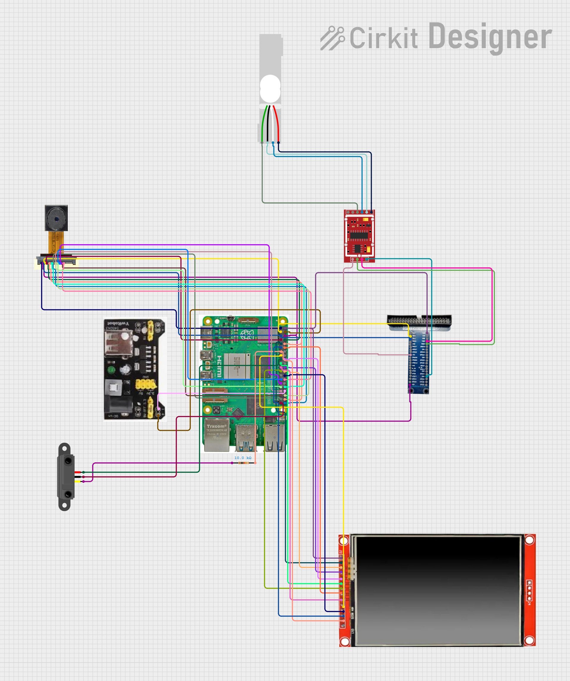
Explore Projects Built with OpenCrBoard
Common Applications and Use Cases
- Robotics projects, including mobile robots and robotic arms
- IoT devices for smart home automation
- Educational tools for learning embedded systems and programming
- Prototyping sensor-based systems
- Actuator control for hobbyist projects
Technical Specifications
Key Technical Details
- Microcontroller: STM32F746 (ARM Cortex-M7, 32-bit, 216 MHz)
- Operating Voltage: 3.3V
- Input Voltage: 6.5V to 16V
- Connectivity:
- Bluetooth 4.0
- Wi-Fi (via external module)
- USB 2.0
- I/O Pins:
- 40 GPIO pins (digital and analog)
- 6 PWM outputs
- 4 UART ports
- 2 I2C ports
- 1 SPI port
- Memory:
- 1 MB Flash
- 320 KB SRAM
- Dimensions: 90 mm x 60 mm
- Weight: 50 g
Pin Configuration and Descriptions
The OpenCrBoard features a comprehensive pin layout to support a variety of peripherals. Below is the pin configuration:
| Pin Name | Type | Description |
|---|---|---|
| VIN | Power Input | Input voltage (6.5V to 16V) |
| GND | Ground | Ground connection |
| 3.3V | Power Output | 3.3V regulated output for external components |
| GPIO1-40 | Digital/Analog | General-purpose I/O pins |
| PWM1-6 | PWM Output | Pulse-width modulation outputs for motor control |
| UART1-4 | Communication | UART serial communication ports |
| I2C1, I2C2 | Communication | I2C communication ports |
| SPI | Communication | SPI communication port |
| USB | Communication | USB 2.0 interface for programming and data |
Usage Instructions
How to Use the OpenCrBoard in a Circuit
Powering the Board:
- Connect a power source to the VIN pin (6.5V to 16V) or use the USB port for power and programming.
- Ensure the GND pin is connected to the ground of your circuit.
Connecting Sensors and Actuators:
- Use the GPIO pins for digital or analog input/output.
- For motor control, connect motor drivers to the PWM pins.
- Use the I2C or SPI ports for communication with compatible sensors or modules.
Programming the Board:
- Connect the board to your computer via USB.
- Use the Arduino IDE or a compatible development environment to write and upload code.
Wireless Communication:
- For Bluetooth, pair the board with your device and use a serial communication library.
- For Wi-Fi, connect an external Wi-Fi module to the UART or SPI port and configure it in your code.
Important Considerations and Best Practices
- Always check the voltage and current ratings of connected components to avoid damage.
- Use appropriate pull-up or pull-down resistors for GPIO pins when necessary.
- Avoid exceeding the maximum current output of the 3.3V pin (typically 50 mA).
- Ensure proper heat dissipation if the board is used in high-power applications.
- Use decoupling capacitors near power pins to reduce noise in the circuit.
Example Code for Arduino UNO Compatibility
The OpenCrBoard can be programmed using the Arduino IDE. Below is an example of how to read a sensor value and control an LED:
// Define pin numbers
const int sensorPin = A0;  // Analog pin connected to the sensor
const int ledPin = 13;     // Digital pin connected to the LED

void setup() {
  pinMode(ledPin, OUTPUT);  // Set LED pin as output
  pinMode(sensorPin, INPUT); // Set sensor pin as input
  Serial.begin(9600);       // Initialize serial communication
}

void loop() {
  int sensorValue = analogRead(sensorPin); // Read sensor value
  Serial.print("Sensor Value: ");          // Print sensor value to serial monitor
  Serial.println(sensorValue);

  if (sensorValue > 500) {  // If sensor value exceeds threshold
    digitalWrite(ledPin, HIGH); // Turn on LED
  } else {
    digitalWrite(ledPin, LOW);  // Turn off LED
  }

  delay(100); // Wait for 100 ms before next reading
}
Troubleshooting and FAQs
Common Issues and Solutions
Board Not Powering On:
- Cause: Insufficient input voltage or incorrect power connection.
- Solution: Ensure the VIN pin receives 6.5V to 16V or use a USB connection.
Unable to Upload Code:
- Cause: Incorrect board or port selected in the Arduino IDE.
- Solution: Verify that the correct board and COM port are selected in the IDE settings.
Bluetooth Not Connecting:
- Cause: Device not discoverable or incorrect pairing procedure.
- Solution: Ensure the board is in pairing mode and use the correct pairing code.
Wi-Fi Module Not Responding:
- Cause: Incorrect wiring or configuration.
- Solution: Double-check the connections to the UART or SPI port and verify the module's firmware.
Sensor Readings Are Inaccurate:
- Cause: Electrical noise or incorrect wiring.
- Solution: Use shielded cables, add decoupling capacitors, and verify sensor connections.
Additional Tips
- Use the serial monitor in the Arduino IDE to debug your code and monitor sensor data.
- Refer to the OpenCrBoard datasheet for detailed pinout diagrams and advanced features.
- Regularly update the firmware to ensure compatibility with the latest libraries and tools.