How to Use Metal touch sensor: Examples, Pinouts, and Specs
Introduction
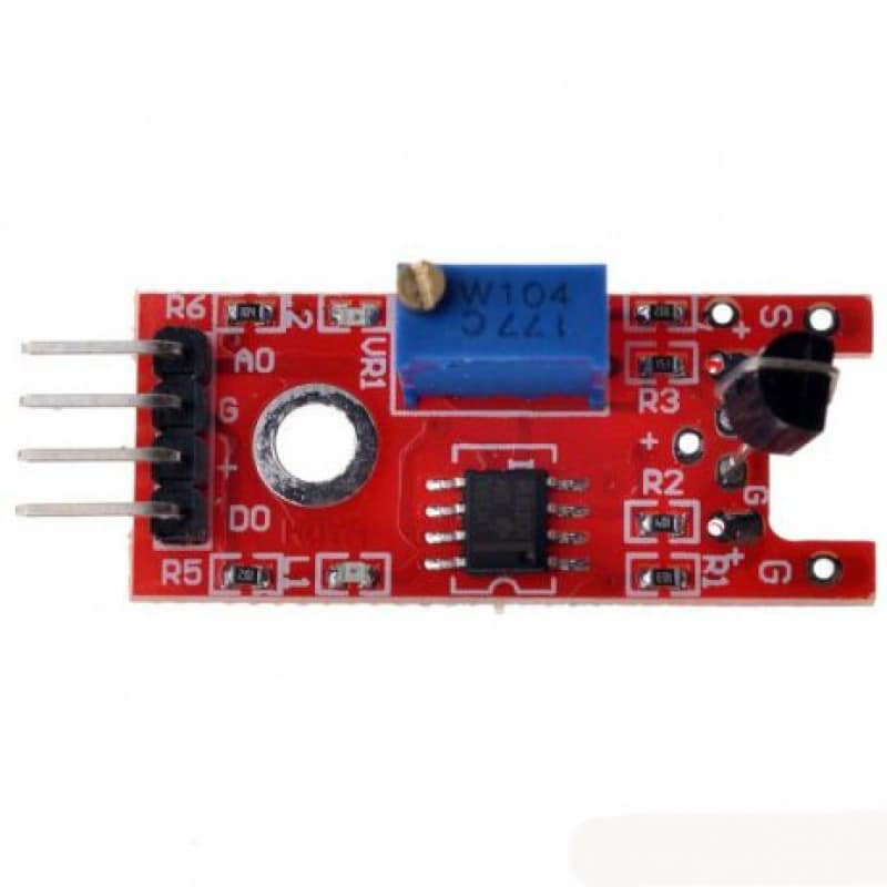
The Metal Touch Sensor is a versatile electronic component designed to detect the touch or proximity of a metal object. This sensor is commonly used in touch-sensitive applications, such as touch-activated switches, interactive displays, and security systems. Its ability to detect metal objects makes it ideal for various industrial and consumer electronics projects.
Explore Projects Built with Metal touch sensor
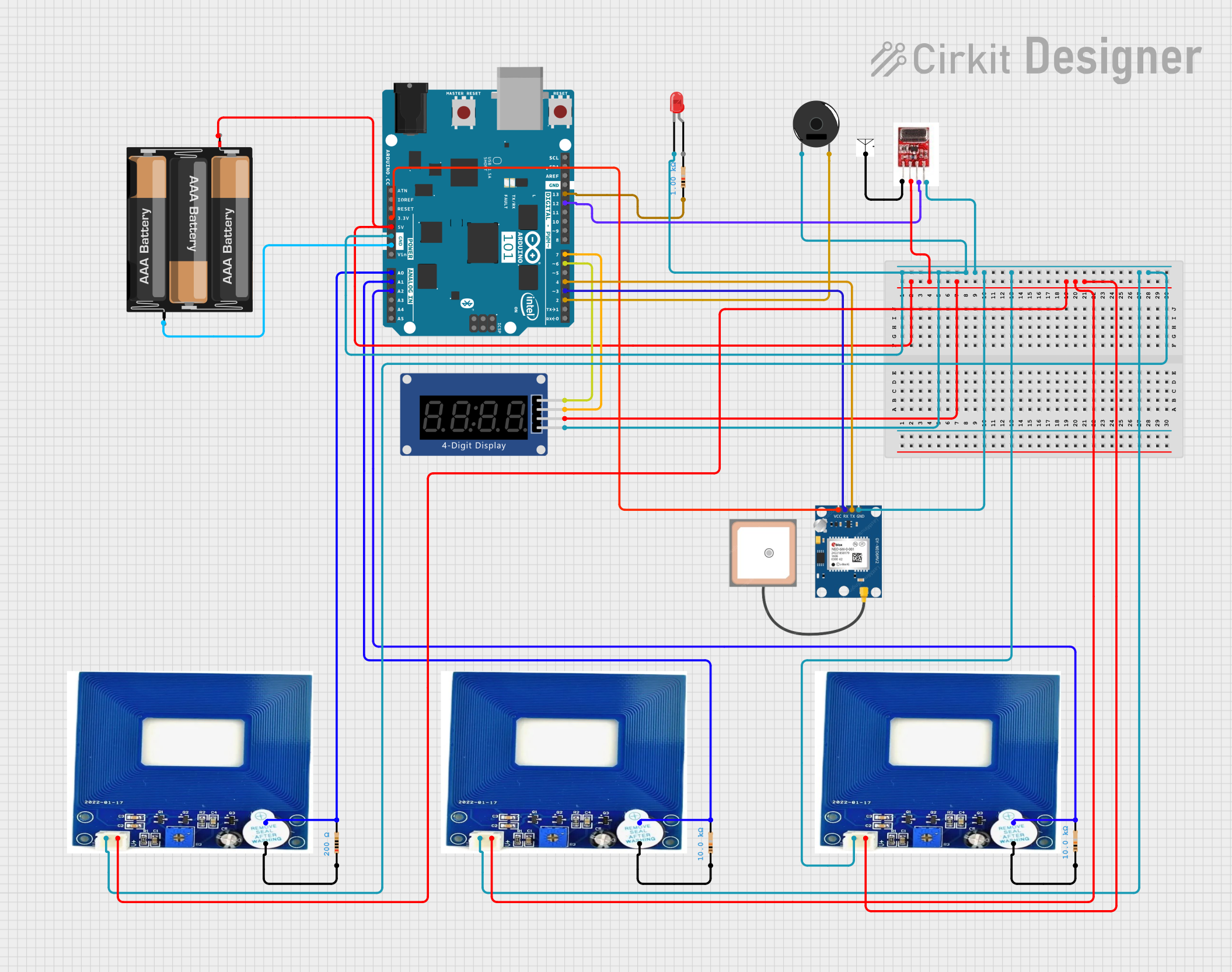
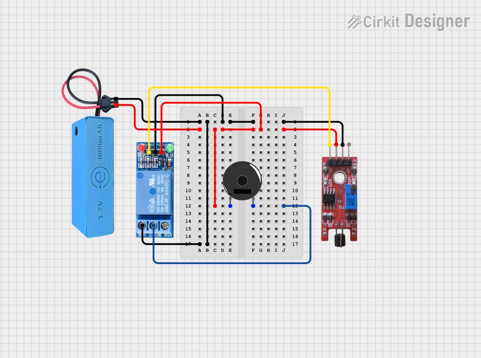

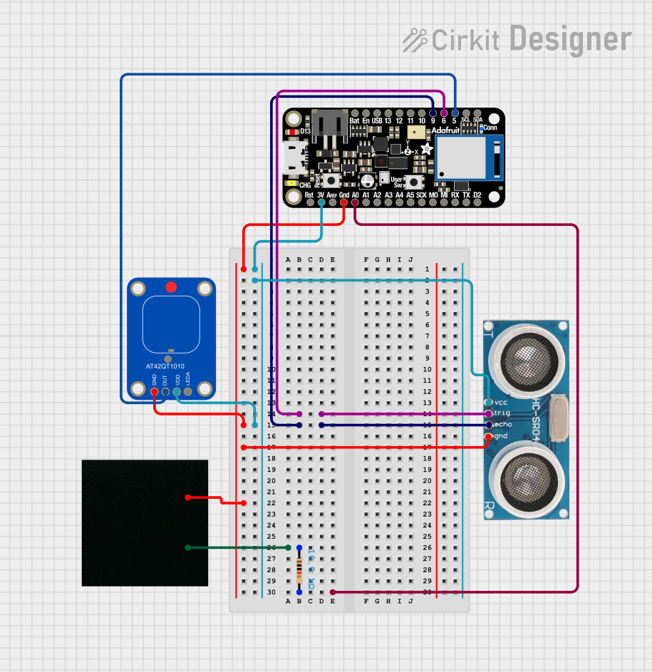
Explore Projects Built with Metal touch sensor
Technical Specifications
Key Technical Details
| Parameter | Value |
|---|---|
| Operating Voltage | 3.3V - 5V |
| Operating Current | < 10mA |
| Output Type | Digital (High/Low) |
| Response Time | < 60ms |
| Detection Range | 0 - 3mm |
| Operating Temperature | -20°C to 70°C |
| Dimensions | 28mm x 20mm x 8mm |
Pin Configuration and Descriptions
| Pin Number | Pin Name | Description |
|---|---|---|
| 1 | VCC | Power supply (3.3V - 5V) |
| 2 | GND | Ground |
| 3 | OUT | Digital output signal (High/Low) |
Usage Instructions
How to Use the Component in a Circuit
- Power Supply: Connect the VCC pin to a 3.3V or 5V power supply.
- Ground Connection: Connect the GND pin to the ground of your circuit.
- Output Signal: Connect the OUT pin to a digital input pin of your microcontroller (e.g., Arduino UNO).
Example Circuit Diagram
  +5V  --------------------+
                          |
                         [VCC]
                          |
                         [OUT] ----> Digital Input Pin (e.g., D2 on Arduino)
                          |
                         [GND]
                          |
  GND  --------------------+
Important Considerations and Best Practices
- Power Supply: Ensure that the power supply voltage is within the specified range (3.3V - 5V).
- Debouncing: Implement software debouncing to avoid false triggers due to noise.
- Environmental Factors: Be aware of environmental factors such as temperature and humidity, which may affect sensor performance.
- Metal Object Size: The size and shape of the metal object can influence the detection range and sensitivity.
Sample Arduino Code
// Metal Touch Sensor Example Code
// Connect the sensor's OUT pin to Arduino digital pin 2

const int sensorPin = 2; // Pin connected to the sensor's OUT pin
const int ledPin = 13;   // Pin connected to the onboard LED

void setup() {
  pinMode(sensorPin, INPUT); // Set sensor pin as input
  pinMode(ledPin, OUTPUT);   // Set LED pin as output
  Serial.begin(9600);        // Initialize serial communication
}

void loop() {
  int sensorValue = digitalRead(sensorPin); // Read the sensor value

  if (sensorValue == HIGH) {
    digitalWrite(ledPin, HIGH); // Turn on the LED if sensor is triggered
    Serial.println("Metal detected!");
  } else {
    digitalWrite(ledPin, LOW);  // Turn off the LED if no metal is detected
    Serial.println("No metal detected.");
  }

  delay(100); // Small delay to avoid rapid toggling
}
Troubleshooting and FAQs
Common Issues Users Might Face
- False Triggers: The sensor may produce false triggers due to electrical noise or environmental factors.
- No Detection: The sensor may fail to detect metal objects if they are too small or too far away.
- Intermittent Operation: The sensor may work intermittently if there are loose connections or unstable power supply.
Solutions and Tips for Troubleshooting
- False Triggers: Implement software debouncing and ensure proper grounding to minimize noise.
- No Detection: Ensure the metal object is within the specified detection range and of adequate size.
- Intermittent Operation: Check all connections and ensure a stable power supply. Use capacitors to filter out power supply noise if necessary.
FAQs
Q: Can the Metal Touch Sensor detect non-metallic objects? A: No, the sensor is specifically designed to detect metal objects.
Q: What is the maximum detection range of the sensor? A: The maximum detection range is approximately 3mm.
Q: Can I use the sensor with a 3.3V microcontroller? A: Yes, the sensor can operate with a power supply voltage of 3.3V to 5V.
Q: How can I increase the sensitivity of the sensor? A: Sensitivity can be adjusted by changing the size and shape of the metal object or by modifying the sensor's circuitry.
Q: Is the sensor affected by temperature changes? A: The sensor operates within a temperature range of -20°C to 70°C, but extreme temperatures may affect its performance.
This documentation provides a comprehensive guide to understanding, using, and troubleshooting the Metal Touch Sensor. Whether you are a beginner or an experienced user, this guide aims to help you effectively integrate the sensor into your projects.